
Two RF cable assemblies can use the same connector interface and the same cable family, but perform differently simply because the length is different.
This is a common situation in high-frequency projects. A customer may ask whether the same 40 GHz cable assembly can be supplied in 300 mm, 500 mm and 1000 mm versions. Mechanically, all three may be possible. Electrically, they should not be treated as the same assembly.
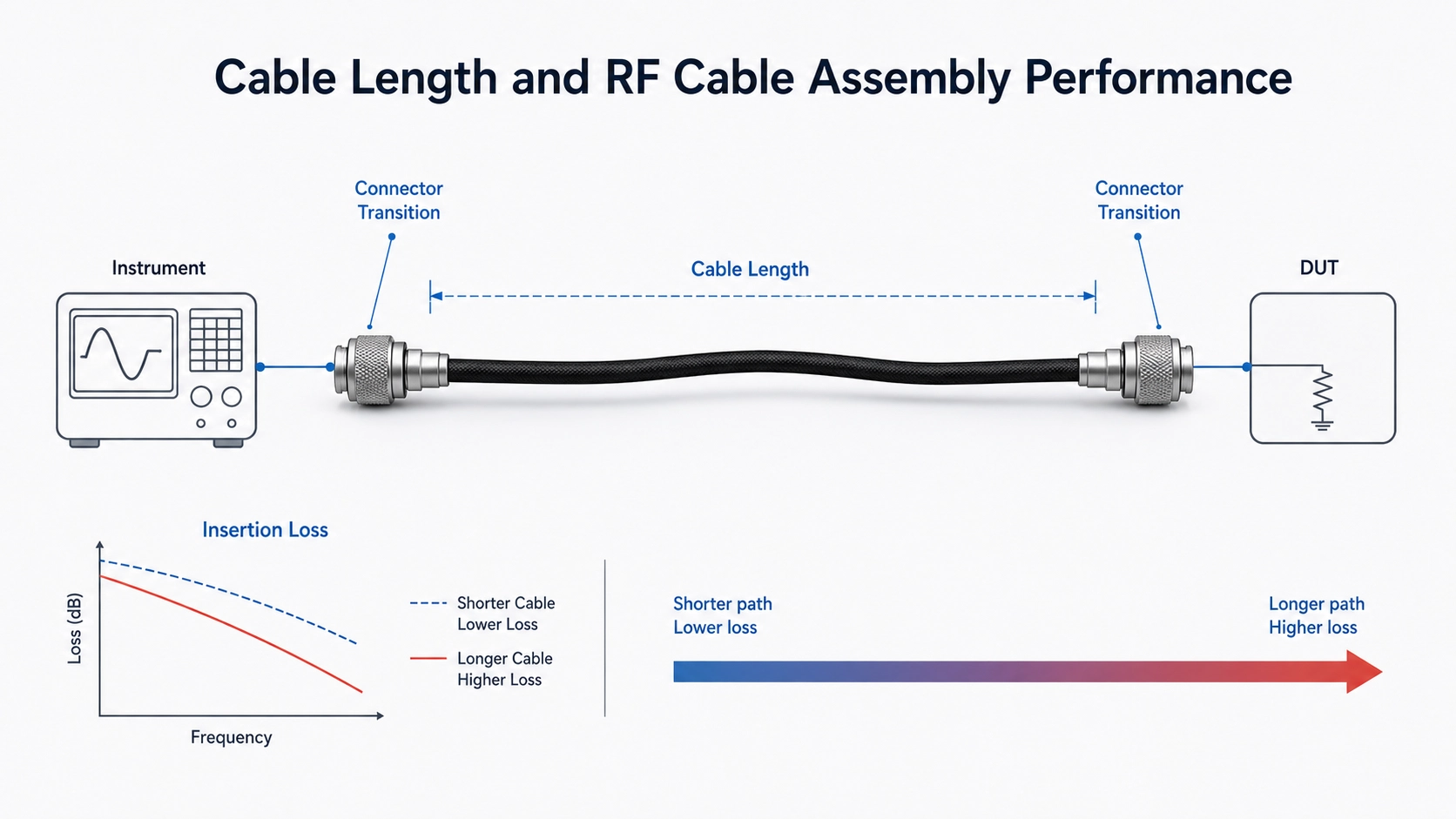
At microwave and millimeter-wave frequencies, cable length affects insertion loss, routing, bend radius, phase behavior, handling stability and the need for assembly-level RF test data. A connector rated to 40 GHz or 67 GHz does not guarantee that every cable length using that connector will meet the same system requirement.
Typical Customer Question
“We need the same 2.92mm cable assembly in 300 mm, 500 mm and 1000 mm. Can they all be used up to 40 GHz?” The practical answer is: the connector may support the frequency, but the finished cable assembly still needs to be checked by length, cable type, routing condition and insertion loss target.
Quick engineering judgment: Longer RF cable assemblies usually have higher insertion loss and are more sensitive to routing, bending and handling. At high frequencies, cable length should be reviewed together with frequency range, cable family, connector interface, bend radius and assembly-level RF test data.
This article explains how cable length affects RF cable assemblies, why connector frequency rating is not enough, and what engineers should specify when ordering custom RF cable assemblies.
The 300 mm, 500 mm and 1000 mm Problem
When a cable assembly is short, the total cable loss may be low enough that the project still has margin. As the same assembly becomes longer, the cable loss accumulates across the full path. At higher frequencies, this difference becomes more visible.
For example, a 300 mm assembly may be acceptable for a compact microwave module connection. A 500 mm version may still work if the loss budget is not too tight. A 1000 mm version may require a lower-loss cable family, a shorter routing path, or assembly-level insertion loss verification before it can be approved.
The important point is not that “longer is always bad.” The point is that length changes the RF path and should be reviewed as part of the electrical design, not only as a mechanical dimension.
What Actually Changes When Cable Length Increases
| What changes | Why it matters | What to check |
|---|---|---|
| Insertion loss increases | Longer cable paths consume more signal margin. | Cable family, length and assembly-level loss data. |
| Routing becomes more complex | Extra length can create loops, tight bends or unsupported sections. | Bend radius, strain relief and final installation path. |
| Handling sensitivity may increase | Longer test cables are often moved more during setup changes. | Phase stability, amplitude repeatability and cable movement after calibration. |
| Connector transition becomes more visible | At high frequencies, cable and connector transitions must work as one RF path. | Connector interface, termination quality and VSWR / return loss requirement. |
Connector Frequency Rating Is Not the Whole Answer
A 2.92mm, 2.4mm or 1.85mm connector may support high-frequency operation, but the finished cable assembly is not defined by connector rating alone. The cable type, length, connector-to-cable transition, termination process and routing condition all contribute to final performance.
This is why a request such as “2.92mm cable assembly, 40 GHz, 1000 mm” still needs review. The connector interface may be appropriate, but the cable family and length may need adjustment if the insertion loss target is tight.
For connector interface selection, review Vinstronics 2.92mm RF connectors, 2.4mm RF connectors and 1.85mm RF connectors.
When Length Becomes a Loss Budget Issue
Cable length becomes critical when the system already has a tight insertion loss budget. This often happens in longer microwave interconnects, high-frequency test paths, antenna or RF front-end connections, and module-to-module RF links.
If the requested length pushes the assembly close to the loss limit, engineers should consider one or more of these actions:
- Shorten the RF path if the mechanical layout allows it.
- Move to a lower-loss cable family for the required frequency and length.
- Review whether the connector interface is suitable for the operating frequency.
- Reduce unnecessary adapters or transitions in the final path.
- Request assembly-level insertion loss and return loss data.
- Check whether the installed bend radius creates additional mechanical stress.
For projects where the loss budget is already tight, see low-loss RF cable assemblies for microwave interconnects with tight loss budgets.
Length Means Different Things in Different Applications
In an installed microwave interconnect, cable length usually affects loss budget, routing and system margin. In a VNA or RF test cable, length also affects how the cable is handled after calibration. In a fixed internal path, length and shape may be controlled more tightly by the module layout.
This difference matters because the same cable length can be acceptable in one application and risky in another. A 1000 mm cable used as a static rack interconnect may have a different risk profile from a 1000 mm test cable that is moved throughout the day.
For VNA and repeatable measurement applications, review phase-stable RF cable assemblies for repeatable VNA measurements. For fixed internal microwave routing, see semi-rigid RF cable assemblies for microwave modules and fixed RF paths.
When a Longer Cable Needs a Different Cable Family
A longer cable does not always mean the project will fail. But it may mean that the cable family should change.
A short flexible jumper may work well at a certain frequency. A longer version of the same assembly may require a lower-loss cable type, a larger cable diameter, a more stable structure or a different routing plan. If the cable is used in a calibrated test setup, phase stability and handling repeatability may also become part of the decision.
This is where cable and connector selection should be reviewed together. The assembly should be treated as one RF path, not as a cable part number plus two connectors. See cable and connector selection for custom RF cable assemblies.
What Engineers Should Specify Before Ordering
A useful RF cable assembly request should explain both the required length and the electrical requirement behind that length. This helps avoid a situation where the cable can be manufactured, but the final RF path does not meet the real system need.
Before requesting quotation, provide:
- Operating frequency range
- Required cable length
- Connector interface and gender at both ends
- Maximum insertion loss target, if defined
- VSWR or return loss requirement
- Whether the cable is static, moved occasionally or handled frequently
- Minimum bend radius or routing limitation
- Power level, if relevant
- Environmental condition, if special
- Required assembly-level RF test data
For a broader RFQ checklist, review the RF Cable Assemblies Guide.
Practical Takeaway
Cable length is not just a dimension on a drawing. At high frequencies, it changes the electrical and mechanical behavior of the finished RF cable assembly.
Before approving a length, review the frequency range, insertion loss budget, cable family, connector interface, bend radius and test data requirement together. In some projects, shortening the path is the best solution. In others, a lower-loss, phase-stable or semi-rigid cable assembly may be more appropriate.
The goal is not simply to make the cable longer or shorter. The goal is to keep the final RF path suitable for the actual system.
FAQ
Does cable length affect RF cable assembly performance?
Yes. Longer RF cable assemblies usually have higher insertion loss and may be more sensitive to routing, bending and handling. The effect becomes more important at high frequencies.
Can the same connector support different cable lengths at the same frequency?
Mechanically, yes. Electrically, the final assembly performance still depends on cable type, length, connector transition, termination and test requirement. Connector frequency rating alone is not enough.
Does a longer RF cable always need a low-loss cable?
Not always. It depends on frequency range, length, loss budget and system margin. Longer high-frequency paths often require lower-loss cable families, but the final decision should be based on the full assembly requirement.
What information should I provide for a custom RF cable assembly?
Provide frequency range, length, connector pair, insertion loss target, VSWR or return loss requirement, routing space, bend radius, movement condition and required RF test data.
Need help reviewing RF cable length for a high-frequency assembly?
Send your frequency range, target length, connector pair, routing space, insertion loss target and test data requirement. Vinstronics can help review whether the requested length is suitable for your RF path.

