
2.92mm Precision RF Connectors
2.92mm / K precision RF connectors for DC–40 GHz microwave interconnects.
2.92mm RF connectors, also known as K connectors, are precision 50 Ω microwave coaxial interfaces used in test equipment, RF modules, PCB launches, feedthroughs and panel-mounted systems.

Quick selection by structure
Choose the 2.92mm connector structure by board transition, panel mounting, feedthrough path or solderless validation requirement.
End Launch PCB Connectors
For board-edge microwave transitions where trace geometry, grounding pattern and connector registration define the launch quality.
Vertical Solderless PCB Connectors
For repeatable PCB validation without soldering, especially when test boards or prototypes need removable RF ports.
Feedthrough Connectors
For enclosure, module wall and panel transitions where the RF path must pass through a defined mechanical boundary.
Flange Mount Connectors
For mechanically stable panel interfaces, fixtures and front-panel ports where mounting geometry must be controlled.
Cable Interface Matching
For cable assembly interfaces where the connector structure must match the cable, panel or module-side requirement.
Not sure which 2.92mm structure fits your layout? Send a drawing, PCB layout or panel sketch for connector matching.
Send Drawing for Connector MatchFeatured 2.92mm connector types
Representative products from the current 2.92mm connector archive, selected to show solderless PCB, vertical launch, PCB adapter and end launch paths.

42.5 Ohm 2.92mm Solderless PCB Connector
For low-impedance PCB launches where controlled transition geometry and repeatable solderless mounting matter.
- DC–40 GHz 2.92mm jack interface.
- 42.5 Ω structure for low-impedance board environments.
- Solderless compression mount for repeatable board-side installation.
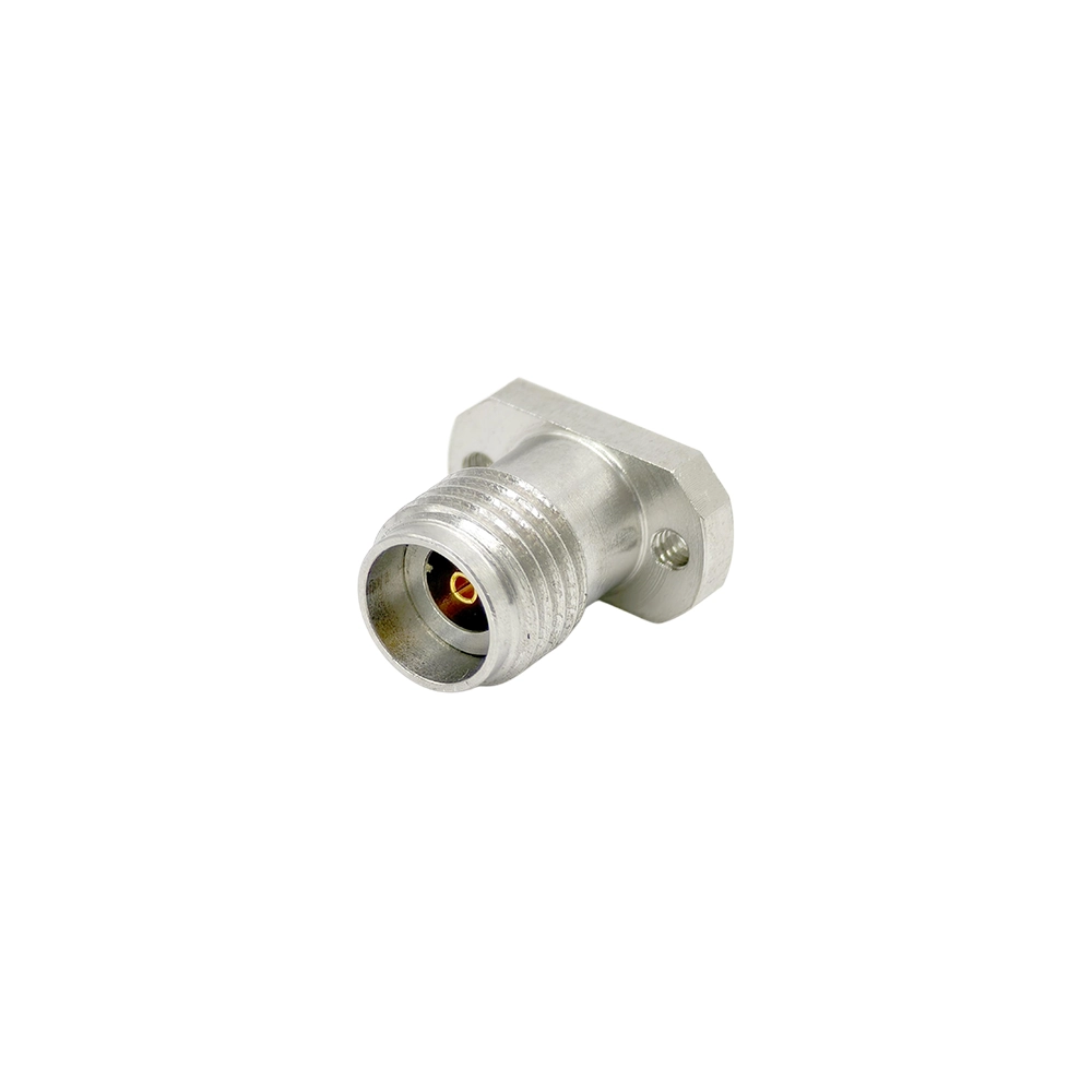
Vertical Solderless Female Connector
For compact vertical PCB launches where solderless installation and a controlled 50 Ω transition matter.
- DC–40 GHz 2.92mm female vertical launch connector.
- Two-hole flange for stable mechanical grounding.
- Suitable for precision test boards, fixtures and RF validation.

PCB Adapter Connector
For compact connector-to-board transitions where board thickness and transition geometry define the fit.
- 2.92mm K interface for board-level RF transition.
- Used for RF boards, test boards and compact modules.
- Selection depends on contact geometry and board thickness.
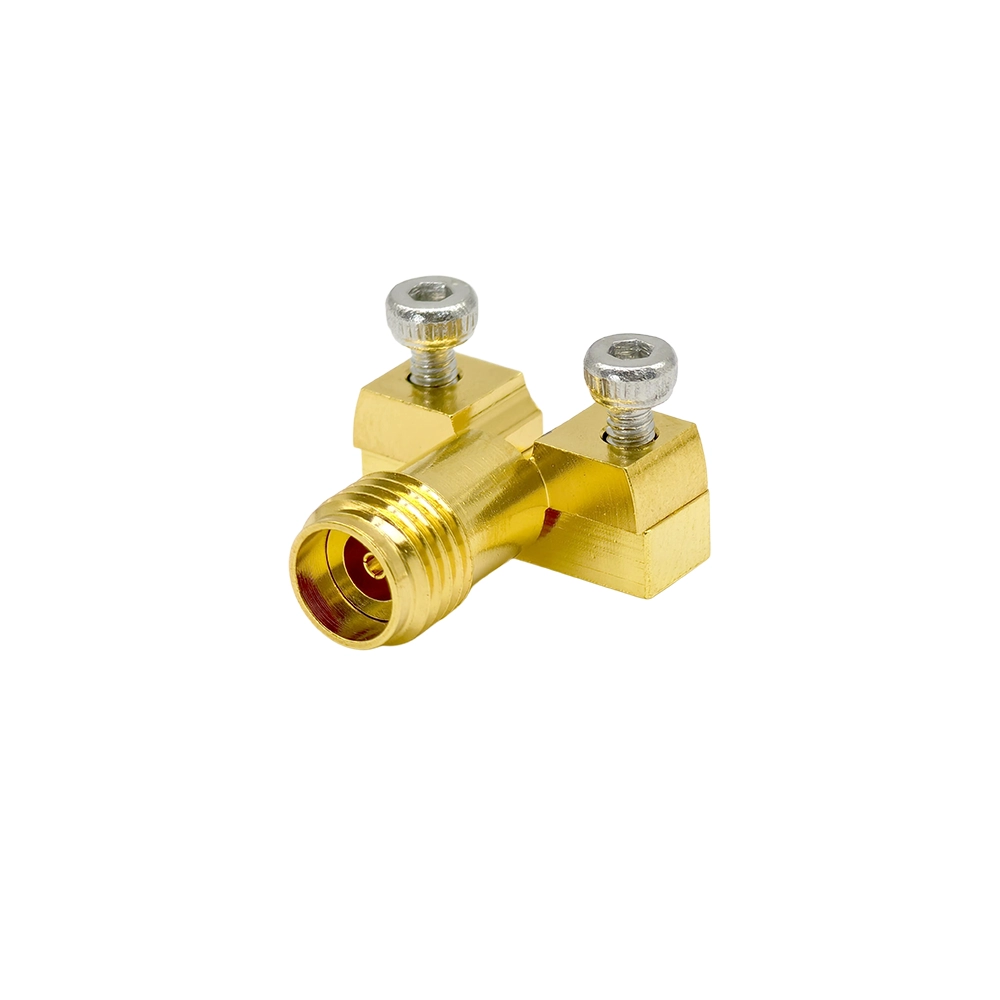
End Launch PCB Connector
For controlled board-edge RF transitions where connector-to-PCB registration affects continuity.
- 2.92mm female end launch PCB mount structure.
- Designed for board-edge microwave trace transitions.
- Suitable for fixtures, evaluation boards and RF modules.
Want to browse all currently published 2.92mm connector products?
View all 2.92mm connector products →What is a 2.92mm / K connector?
A 2.92mm connector, also called a K connector, is a precision 50 Ω microwave coaxial interface commonly used for DC to 40 GHz signal transmission. It is selected for high-frequency test systems, RF modules, PCB launch structures, feedthrough transitions and precision panel-mounted interconnects.
Core engineering position
- Precision 50 Ω coaxial interface.
- Typical use up to 40 GHz.
- Common in microwave test and RF modules.
- Available in PCB, panel, feedthrough and cable structures.
2.92mm vs SMA, 3.5mm and 2.4mm connectors
The 2.92mm / K interface is often selected when a compact precision connector is required for DC–40 GHz systems, especially where SMA is not sufficient and 2.4mm may be more than required.
SMA
General RF and lower-cost microwave links, usually below precision 40 GHz use cases.
3.5mm
Precision microwave testing below the 2.92mm ceiling, commonly used in controlled lab systems.
2.92mm / K
DC–40 GHz precision microwave interconnects for test, PCB launch and compact RF module applications.
2.4mm
Higher-frequency precision systems, often selected near 50 GHz applications.
What to confirm before quotation
After choosing the connector structure, confirm the mechanical and electrical inputs that determine the final 2.92mm connector match.
| Requirement | Why it matters | Useful input |
|---|---|---|
| PCB stack-up | Defines launch height, grounding path and transition geometry. | Board thickness, dielectric, trace type and footprint. |
| Panel or wall thickness | Affects feedthrough length, flange seating and rear-side clearance. | Panel drawing, wall thickness and mounting direction. |
| Mating interface | Confirms gender, thread condition and compatibility with the target system. | Mating connector family, gender and use environment. |
| Frequency target | Helps confirm whether the structure is suitable for DC–40 GHz use. | Operating band, test margin and expected installation condition. |
| Mounting pattern | Ensures the connector can be installed into the fixture, module or panel. | Hole pattern, screw size, flange space and keep-out area. |
Download the 2.92mm RF Connectors Selection Guide
Review DC–40 GHz K connector structures for PCB launch, solderless mounting, feedthrough, flange and panel applications.
Common 2.92mm connector questions
What is a 2.92mm RF connector?
A 2.92mm RF connector is a precision microwave coaxial interface commonly used for DC to 40 GHz applications.
Is a 2.92mm connector the same as a K connector?
Yes. 2.92mm connectors are widely referred to as K connectors in precision microwave interconnect selection.
What frequency range do 2.92mm connectors support?
This page focuses on 2.92mm / K connector structures for DC to 40 GHz applications. Final performance depends on structure, launch and mating condition.
Can 2.92mm connectors mate with SMA or 3.5mm connectors?
2.92mm connectors are often mechanically compatible with 3.5mm and SMA-type interfaces, but mating condition should be checked before integration. For precision systems, confirm the interface, wear condition and frequency target.
When should I choose 2.92mm instead of 2.4mm?
Choose 2.92mm when the target system is within DC–40 GHz and a compact precision K interface is preferred. Choose 2.4mm when additional frequency margin above 40 GHz is required.
What is a 2.92mm end launch connector used for?
A 2.92mm end launch connector transitions a microwave signal from a board-edge transmission line into a coaxial K connector interface. It is commonly used on RF test boards, fixtures and compact microwave modules.
What is a 2.92mm solderless PCB connector?
A 2.92mm solderless PCB connector uses mechanical compression instead of soldering to create a removable board-level RF transition. It is useful for repeated validation, test boards and prototype environments.
What information is required for a 2.92mm connector quotation?
Please provide target frequency, connector gender, mounting structure, PCB thickness or panel thickness, transmission line type, drawing or layout file, quantity and application environment.
Can Vinstronics provide drawing-based connector selection?
Yes. Send the drawing, PCB layout, panel structure or feedthrough dimensions, and Vinstronics can help identify the suitable 2.92mm connector structure for quotation review.
Are custom 2.92mm connector structures available?
Custom or application-specific structures can be reviewed based on drawing, installation geometry and electrical requirements. Share the mechanical limits and target use case for engineering evaluation.
Need help matching a 2.92mm connector?
Send your drawing, PCB layout or panel requirement for structure review and model recommendation.