
“Low-loss RF cable assembly, 40 GHz, 500 mm” sounds like a clear request.
For quotation, it is a useful start. For engineering review, it is still incomplete.
The phrase does not tell the supplier the maximum acceptable insertion loss, the exact test frequency range, the connector pair, the routing condition, or whether assembly-level test data is required. At high frequencies, those missing details can decide whether the finished cable assembly meets the real system requirement.
Common RFQ Mistake
Many requests specify the cable as “low loss” but do not define the insertion loss target. Without frequency range, cable length, connector interface and test data requirement, the finished RF path cannot be judged only from the cable description.
Quick engineering judgment: RF cable assembly insertion loss is the result of the finished assembly, not only the bulk cable attenuation. Cable length, connector transitions, termination quality, routing condition and measurement frequency all affect the final value.
This article explains what affects insertion loss in RF cable assemblies, when typical data may be enough, and what engineers should specify before ordering custom RF cable assemblies.
Insertion Loss Is a Finished Assembly Result
Bulk cable attenuation is only one part of the story. A cable datasheet may show the expected attenuation of the cable itself, but a finished RF cable assembly includes more than cable.
The assembly also includes two connector interfaces, connector-to-cable transitions, the termination process, physical length, bend condition and any additional adapters used in the final path. At higher frequencies, these details become more visible.
That is why an engineer should be careful with statements such as “this cable is low loss.” The more useful question is:
What insertion loss does the finished cable assembly need to meet at the required frequency and length?
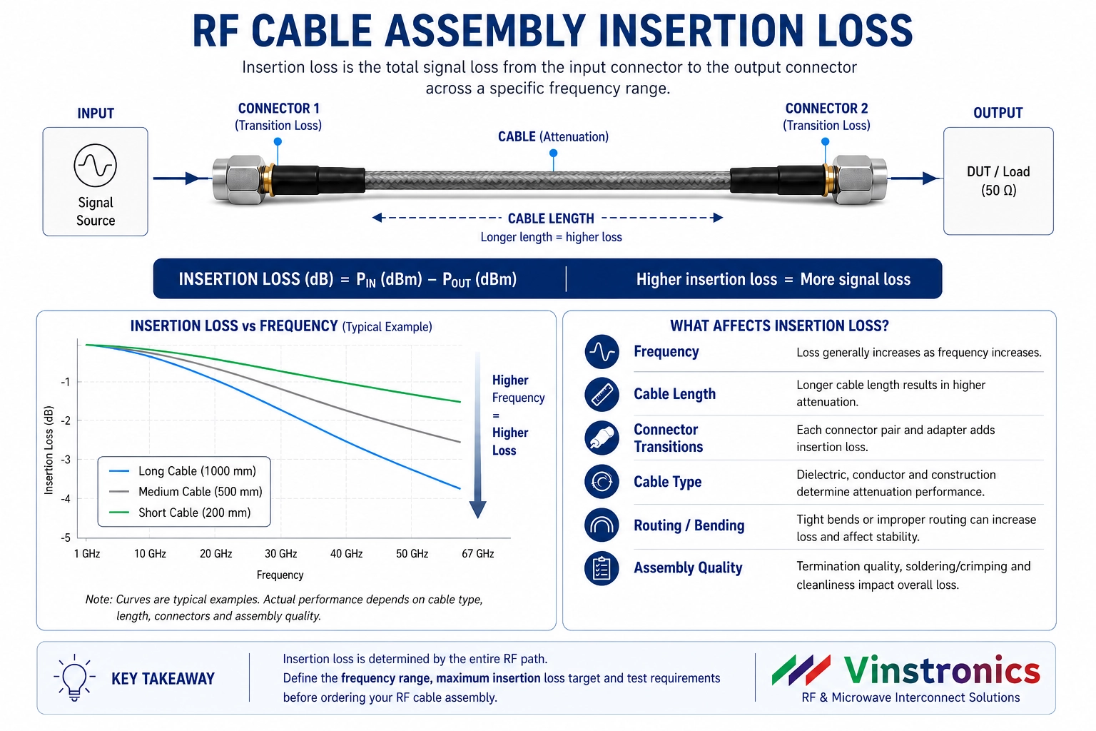
What Affects RF Cable Assembly Insertion Loss?
For most high-frequency cable assembly projects, insertion loss should be reviewed as a combination of electrical and mechanical factors.
| Factor | How it affects insertion loss | What engineers should check |
|---|---|---|
| Cable length | Longer cable paths usually increase total loss. | Target length, loss budget and whether a lower-loss cable family is needed. |
| Operating frequency | Loss generally becomes more critical as frequency increases. | Required frequency range and test points, not only the maximum frequency. |
| Connector transition | Mismatch and transition quality can add loss and affect return loss. | Connector interface, gender, mating condition and termination method. |
| Cable family | Different cable structures have different attenuation and flexibility. | Low-loss, phase-stable, semi-rigid or flexible cable requirement. |
| Routing and bend radius | Tight bends or stressed routing can affect performance and reliability. | Installation space, minimum bend radius and strain near connectors. |
| Test requirement | Typical cable data may not prove finished assembly performance. | Whether assembly-level insertion loss / VSWR data is required. |
For a related discussion on length, see how cable length affects RF cable assembly performance. For tight microwave loss budgets, review low-loss RF cable assemblies for microwave interconnects.
Bulk Cable Attenuation vs Assembly Insertion Loss
Bulk cable attenuation is useful for comparing cable families. It helps engineers understand whether one cable type is generally lower loss than another.
Assembly insertion loss is more specific. It reflects the finished cable assembly, including cable length, connectors and termination. For a real RF path, this value is usually more important than the cable attenuation number alone.
This difference matters during sourcing. If an engineer only requests a “low-loss cable,” the supplier may choose a suitable cable family but still need more information to judge whether the finished assembly meets the actual loss target.
For cable material and family selection, see Vinstronics low-loss RF cable. For assembly-level selection, review the RF Cable Assemblies Guide.
When Typical Data May Be Enough
Typical data may be acceptable when the cable assembly is used in a non-critical path, the frequency is moderate, the length is short, and the project does not require a defined maximum insertion loss.
In that case, a supplier can recommend a cable family and connector pair based on frequency range, length and general application. This is often enough for early design review, prototype planning or low-risk interconnects.
However, engineers should be careful when the phrase “low loss” is used without a target. It may mean different things in different projects. A low-loss jumper for one system may not be acceptable in another system with a tighter budget.
When Assembly-Level Test Data Should Be Requested
Assembly-level insertion loss data becomes more important when the cable assembly is part of a calibrated test path, a microwave link, a production test station, or a system with a defined loss budget.
It should also be considered when:
- The cable is long enough that loss may consume system margin.
- The operating frequency is high and connector transitions become more critical.
- The assembly is used in VNA, RF test or measurement-sensitive applications.
- The customer has a maximum insertion loss requirement at specific frequencies.
- The cable routing includes tight bends, movement or mechanical stress.
- Multiple assemblies must perform consistently across a batch.
For projects where cable, connector and termination need to be reviewed together, see cable and connector selection for custom RF cable assemblies.
Common Mistakes to Avoid Before Ordering
The most common problem is not that the customer asks for the wrong cable. It is that the request does not define enough of the finished RF path.
Before ordering, avoid these mistakes:
- Only specifying “low loss” without a maximum insertion loss target.
- Giving the maximum frequency but not the actual test frequency range.
- Assuming connector rating defines the full assembly performance.
- Using cable datasheet attenuation as the finished assembly value.
- Forgetting to specify cable length and routing condition.
- Not clarifying whether test data is required for each assembly.
A clearer RFQ reduces back-and-forth and makes it easier to recommend the correct RF cable assembly from the beginning.
What Engineers Should Specify Before Quotation
A useful insertion loss requirement does not need to be complicated, but it should be specific enough for engineering review.
Before quotation, provide:
- Operating frequency range
- Connector interface and gender at both ends
- Required cable length
- Maximum insertion loss target, if defined
- VSWR or return loss requirement, if relevant
- Cable family preference, if known
- Static installation or frequent movement
- Routing space and bend radius limitation
- Quantity and consistency requirement
- Whether assembly-level test data is required
For a broader RFQ checklist, see Custom RF Cable Assemblies: What Engineers Need to Specify.
Practical Takeaway
Insertion loss should be treated as a finished cable assembly requirement, not just a bulk cable property.
If the project has a defined loss budget, high operating frequency, long cable path or test-data requirement, engineers should specify the insertion loss target clearly before ordering. This helps the supplier review the cable family, connector interface, length, termination and test requirement as one complete RF path.
FAQ
What is RF cable assembly insertion loss?
RF cable assembly insertion loss is the signal loss through the finished cable assembly, including the cable, connectors, transitions and termination effects.
Is insertion loss the same as cable attenuation?
No. Cable attenuation refers to the cable itself, while assembly insertion loss includes cable length, connectors, termination and the finished RF path.
When should I request assembly-level insertion loss test data?
Request assembly-level test data when the application has a tight loss budget, high operating frequency, long cable path, calibrated test setup or batch consistency requirement.
What information is needed to review insertion loss before ordering?
Provide frequency range, connector pair, cable length, maximum insertion loss target, routing condition and whether assembly-level RF test data is required.
Need help reviewing insertion loss for a custom RF cable assembly?
Send your frequency range, connector pair, cable length, maximum insertion loss target, routing condition and required test data. Vinstronics can help review the finished RF path before quotation.

