
In many microwave modules and RF instruments, the cable assembly is not meant to move after installation. It must follow a defined path, hold its shape, preserve shielding and fit inside a limited mechanical space.
That is where semi-rigid RF cable assemblies become useful. They are not selected because they are easier to handle than flexible cables. They are selected because the RF path needs controlled geometry, stable routing and predictable installation inside a fixed system.
Engineer’s Selection Problem
The question is not simply whether a semi-rigid cable can connect two RF ports. The real question is whether the formed assembly can maintain the required RF path, bend geometry, shielding, connector orientation and mechanical fit after it is installed in the module or enclosure.
Short answer: Use semi-rigid RF cable assemblies when the RF path is fixed, routing space is limited, shielding is important and the assembly must hold a defined shape after forming. Use flexible or phase-stable cable assemblies when the cable will be moved, handled or repeatedly reconfigured during testing.
This article explains when to use semi-rigid RF cable assemblies for microwave modules, RF enclosures, instruments, test fixtures and fixed high-frequency interconnect paths. For broader cable selection, see the RF Cable Assemblies Guide.
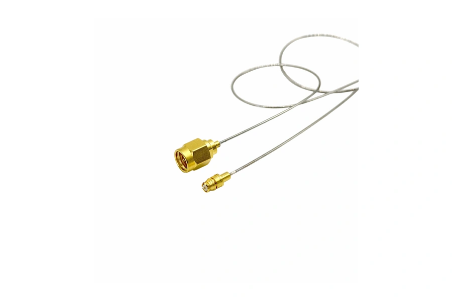
What Makes a Semi-Rigid RF Cable Assembly Different?
A semi-rigid RF cable assembly uses a cable structure that can be formed into a defined route and then hold that shape after installation. Compared with standard flexible cable, it provides a more controlled physical path, stronger shielding and better stability in fixed routing applications.
The important point is that semi-rigid cable is usually not selected for frequent movement. It is selected for fixed RF interconnect paths where the cable should stay in place after forming.
Typical semi-rigid RF cable assembly requirements include:
- Defined cable route inside a module or enclosure
- Controlled bend locations
- Stable connector orientation
- Fixed length and mechanical envelope
- High shielding effectiveness
- Repeatable installation geometry
- Compatibility with microwave module or instrument layout
When Semi-Rigid RF Cable Assemblies Make Sense
Semi-rigid RF cable assemblies are most useful when the cable path is known before installation and will not be changed frequently. They are common in compact RF systems where mechanical routing and electrical performance must be considered together.
| Use condition | Why semi-rigid helps | Engineering note |
|---|---|---|
| Fixed microwave module routing | Holds the defined RF path after forming. | A routing drawing is usually more useful than a simple cable length. |
| Shielded RF enclosure | Supports controlled routing and shielding inside the housing. | Connector orientation and clearance should be checked early. |
| Instrument internal interconnect | Provides stable geometry between internal RF ports. | Avoid forcing the cable into shape during final assembly. |
| Compact test fixture | Fits a fixed path where flexible cable may be too uncontrolled. | Provide photos or mechanical drawings if space is tight. |
| High-frequency fixed path | Helps maintain a repeatable physical path after installation. | Connector, bend radius and cable diameter should be reviewed together. |
When Not to Use Semi-Rigid Cable Assemblies
Semi-rigid cable is not always the best choice. If the cable will be moved frequently, reconfigured often or handled every day in a lab setup, a flexible, ruggedized or phase-stable test cable may be more suitable.
Avoid treating semi-rigid cable as a general replacement for flexible test cable. It is designed for formed, fixed paths, not repeated movement after installation.
Consider other cable options when:
- The cable is moved during daily testing.
- The route changes frequently.
- The user needs repeated connection and disconnection in a lab.
- The cable must tolerate dynamic bending.
- Measurement repeatability after movement is more important than fixed shape.
For applications where cable movement or measurement repeatability matters, phase-stable or ruggedized RF test cables may be a better direction. This related guide compares low loss RF cable vs phase stable RF cable.
Semi-Rigid vs Flexible vs Phase-Stable Cable Assemblies
The best cable assembly depends on the use condition. Semi-rigid cable assemblies solve fixed-routing problems. Flexible and phase-stable cable assemblies solve different problems.
| Cable assembly type | Best used for | Main selection concern |
|---|---|---|
| Semi-rigid RF cable assembly | Fixed internal routing, microwave modules, RF enclosures and instruments. | Bend geometry, connector orientation and mechanical fit. |
| Flexible low-loss cable assembly | System routing where insertion loss and practical flexibility matter. | Insertion loss, length and bend radius. |
| Phase-stable test cable assembly | VNA testing, repeatable measurement and movement-sensitive setups. | Phase repeatability after movement, bending or temperature change. |
| Ruggedized RF test cable assembly | Lab, field and production test handling. | Durability, strain relief and connector protection. |
Common Applications
Semi-rigid RF cable assemblies are often used in applications where the RF path is designed into the mechanical layout. The cable is part of the module structure rather than a loose interconnect.
Common applications include:
- Microwave modules
- RF signal conditioning units
- Frequency converters and synthesizers
- High-frequency instruments
- RF shielded enclosures
- Test fixtures with fixed internal routing
- Aerospace and defense RF assemblies
- Compact system-level RF interconnects
- Internal routing between coaxial ports and PCB transitions
In these applications, the assembly should be reviewed with the mechanical layout, not only with the electrical requirement.
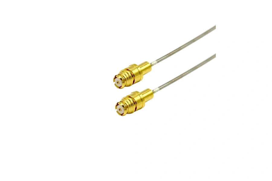
Connector Selection for Semi-Rigid RF Cable Assemblies
The connector interface should match the frequency range, available space, mounting method and mating port. Semi-rigid RF cable assemblies may use interfaces such as SMA, 2.92mm, 2.4mm, 1.85mm, SMP, SMPM or other RF connector families depending on the design requirement.
Connector selection should consider:
- Target frequency range
- Connector gender and orientation
- Straight or right-angle connection
- Panel, module or free-hanging interface
- Available wrench and assembly space
- Mating interface and expected mating cycles
- Whether the assembly connects to a PCB launch, adapter or instrument port
For connector-family review, see Vinstronics precision RF connectors, including 2.92mm RF connectors, 2.4mm RF connectors and 1.85mm RF connectors.
Why a Routing Drawing Matters
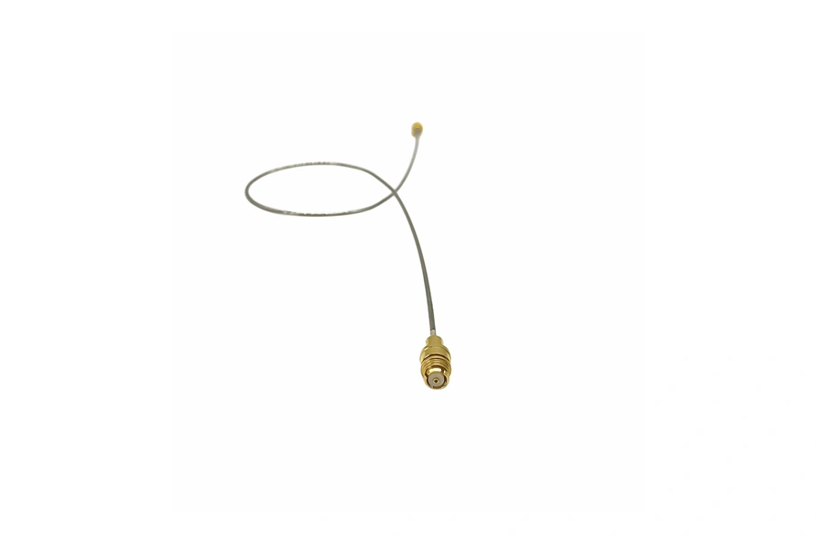
For a semi-rigid RF cable assembly, a single length value is often not enough. The final assembly depends on bend locations, connector orientation, available clearance and how the assembly will be installed.
A useful drawing or sketch should show:
- Connector type and gender on both ends
- Reference points for length measurement
- Bend locations and approximate bend radius
- Connector orientation
- Panel, module or PCB interface locations
- Available clearance around the route
- Any fixed mounting or strain relief points
A marked-up photo can help during early review. For production, a dimensioned drawing is better.
Engineering note: If the route is fixed, do not specify only “SMA to SMA, 200 mm.” The supplier may still need bend geometry, connector orientation and installation clearance to build the correct semi-rigid assembly.
What to Specify Before Requesting a Semi-Rigid Assembly
Before requesting a semi-rigid RF cable assembly recommendation or quote, provide the information that affects both RF performance and mechanical fit.
| Information to provide | Example | Why it matters |
|---|---|---|
| Connector pair | SMA female to SMPM male | Defines interface compatibility and assembly process. |
| Frequency range | DC–26.5 GHz or DC–40 GHz | Supports connector and cable structure review. |
| Routing drawing | Bend path inside a module | Helps confirm shape, clearance and installation fit. |
| Bend radius | Minimum available radius or formed route | Prevents unrealistic forming or mechanical stress. |
| Mechanical envelope | Module height, port spacing, enclosure space | Ensures the assembly fits the actual hardware. |
| Test requirement | VSWR, insertion loss or return loss data | Defines inspection scope and acceptance review. |
For a broader RFQ checklist, see this custom RF cable assembly specification checklist.
Common Selection Mistakes
| Mistake | Why it causes problems | Better approach |
|---|---|---|
| Only specifying connector type and length | The bend route, connector orientation and clearance may still be unclear. | Provide a routing sketch, drawing or installation photo. |
| Using semi-rigid cable for repeated movement | Semi-rigid cable is intended for fixed formed paths, not dynamic flexing. | Use flexible, ruggedized or phase-stable cable for moving setups. |
| Ignoring installation clearance | The assembly may meet RF requirements but fail during installation. | Check port spacing, wrench access and nearby components. |
| Treating the formed cable as adjustable after delivery | Reforming after production can affect fit and assembly quality. | Confirm the route before production when possible. |
How Vinstronics Reviews Semi-Rigid RF Cable Assembly Requirements
Vinstronics reviews semi-rigid RF cable assembly requirements based on the complete fixed-path condition: connector pair, frequency range, cable diameter, routing shape, bend radius, available space and test requirement.
For microwave modules and RF enclosures, the best assembly is usually the one that fits the mechanical route while maintaining the required RF performance. That requires reviewing the cable assembly as part of the system layout, not only as a cable with two connectors.
Related product areas include Vinstronics RF cable assemblies, RF coaxial cable options and precision RF connectors.
FAQ
What is a semi-rigid RF cable assembly?
A semi-rigid RF cable assembly is a formed coaxial interconnect designed to hold a defined shape after installation. It is commonly used for fixed RF routing inside microwave modules, instruments, enclosures and compact systems.
When should I use semi-rigid cable instead of flexible cable?
Use semi-rigid cable when the RF path is fixed, the routing geometry is known, shielding is important and the assembly must hold a defined shape. Use flexible cable when the route changes or the cable is handled frequently.
Is semi-rigid cable suitable for VNA test cables?
Usually not for daily movable test leads. VNA test setups often need phase-stable or ruggedized flexible test cables. Semi-rigid cable is better for fixed internal paths or defined fixture routing.
What information is needed for a semi-rigid cable quote?
Useful information includes connector pair, frequency range, cable length, routing drawing, bend radius, connector orientation, mechanical envelope, quantity and test requirements.
Can semi-rigid RF cable assemblies be custom formed?
Yes. Custom forming is common, but the required bend path, connector orientation and installation space should be defined before production whenever possible.
Need a semi-rigid RF cable assembly for a fixed path?
Send your connector pair, frequency range, routing drawing, bend condition and test requirement. Vinstronics can review whether a semi-rigid, semi-flexible or alternative RF cable assembly structure is more suitable for your module or enclosure.

