
A solderless vertical launch connector may be mechanically compatible with more than one PCB thickness. That does not mean the same RF launch can always be transferred unchanged from one board to another.
For high-frequency test fixtures, two questions should be separated:
Can the connector be mounted correctly on this PCB?
and
Will the connector-to-PCB transition provide the required RF performance on this specific stack-up?
The first is primarily a mechanical compatibility question. The second depends on the actual electromagnetic structure around the launch.
Mechanical board-thickness compatibility does not automatically guarantee an optimized RF launch.
And when a design is transferred to another PCB:
A reference launch should be reviewed against the actual stack-up—not only the total board thickness.
PCB Thickness and Stack-Up Are Different Design Variables
PCB thickness describes the overall physical thickness of the finished board.
PCB stack-up describes how that board is constructed, including the copper layers, dielectric materials, dielectric spacing, routing layers, and PCB ground/reference planes.
Two boards can therefore have the same total thickness while presenting very different RF environments to the connector.
For example, one board may route the signal directly on the top layer over a relatively shallow PCB ground/reference plane. Another board of the same overall thickness may transition into an internal routing layer.
Mechanically, the two boards may look similar to the connector.
Electrically, the transitions are different.
The opposite can also occur. Two boards with different overall thicknesses may have similar local upper-layer RF construction around a top-layer launch.
In that case, the difference in total thickness does not by itself prove that the RF launch must be completely redesigned.
The more useful distinction is:
Total PCB thickness can matter, but it should not be used as a substitute for reviewing the local RF stack-up.
Mechanical Compatibility Comes First
Before evaluating RF performance, confirm that the connector is mechanically compatible with the actual PCB assembly.
Depending on the connector design, this may include:
- supported PCB thickness;
- mounting-screw engagement;
- backside clearance;
- connector seating;
- board support;
- available mounting area.
These requirements are connector-specific.
A connector may support a defined range of PCB thicknesses mechanically, but that should not be interpreted as proof that one identical RF launch geometry is optimized across every supported board.
Mechanical fit first → RF launch review second
The mounting condition also matters after the connector has been selected. Connector seating, alignment, PCB support, and installation consistency remain part of the assembled RF interface.
For more on the mechanical side of this problem, see
Solderless Vertical Launch Connector Repeatability: Mounting Force, Alignment, and Reinstallation
.
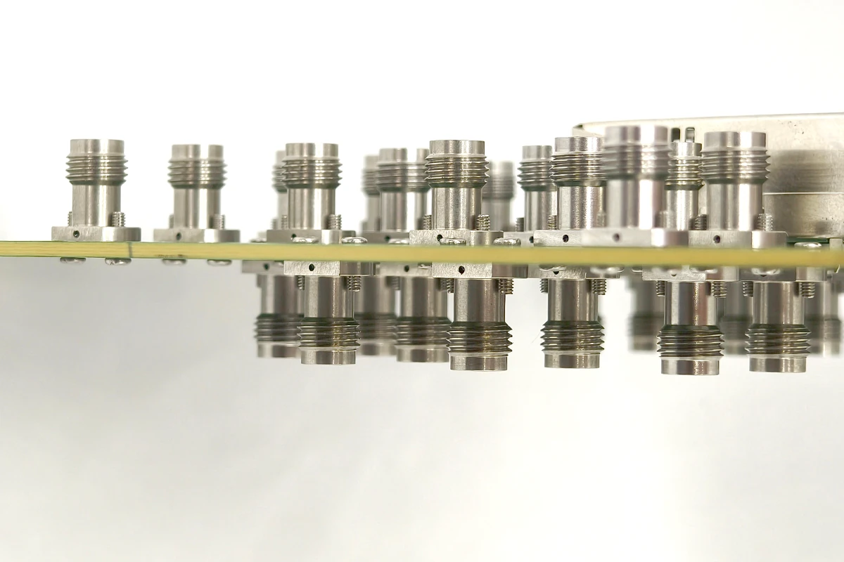
Top-Layer and Internal-Layer Routing Should Be Treated Differently
The PCB routing architecture changes what matters most in the launch.
Top-Layer Microstrip or GCPW
If the connector transitions directly into top-layer microstrip or grounded coplanar waveguide (GCPW), the RF behavior may be governed more directly by the local upper-layer construction than by the total board thickness.
Relevant parameters can include:
- landing and signal-pad geometry;
- trace width;
- coplanar gap where applicable;
- upper dielectric thickness;
- dielectric properties;
- PCB ground/reference-plane depth;
- local ground structure.
Changing one of these parameters changes the electromagnetic environment around the transition even if the finished PCB thickness remains identical.
For this reason:
Two PCBs with the same total thickness should not be assumed to have the same top-layer launch behavior.
Internal-Layer Routing
If the signal must transition from the connector to an internal routing layer, an additional vertical transition becomes part of the RF launch.
Connector → Landing Pad → Signal Via → Internal Transmission Line
In this case, the design may also depend on:
- target routing-layer depth;
- signal-via structure;
- plane clearance / anti-pad geometry;
- surrounding ground structure;
- via-to-trace transition;
- unused via length where applicable.
If a through-via extends through the PCB, changing the board thickness or target routing depth can also change the remaining unused via section.
A blind via, microvia, or backdrilled structure may behave differently, depending on the PCB fabrication approach.
The important point is not that one via technology is universally better.
When the routing layer changes, the vertical transition changes with it.
What Should Be Rechecked When the Stack-Up Changes?
A change in PCB stack-up does not automatically mean every launch dimension must be redesigned.
But the parameters that control the electromagnetic transition should be reviewed.
For a top-layer launch, that usually means checking whether the new PCB preserves the intended:
- dielectric thickness near the launch;
- transmission-line geometry;
- PCB ground/reference-plane relationship;
- local ground structure.
For a via-based internal-layer launch, the review also extends into the board:
- routing depth;
- via geometry;
- plane clearances;
- ground-via structure;
- unused via section;
- via-to-trace transition.
This is the practical reason a PCB launch should not be transferred based on connector model and overall board thickness alone.
As discussed in
How PCB Launch Geometry, Ground Vias, and Return Path Affect Vertical Launch Connector Performance
,
the connector, landing structure, return path, and PCB transmission line form one RF transition.
This article addresses the next question:
How much of that transition is still valid when the PCB construction changes?
When Can a Reference Launch Be Transferred to Another PCB?
A manufacturer-provided reference layout can be a very useful starting point.
The key question is how closely the new PCB matches the conditions for which that launch was developed.
Same Connector, Same Stack-Up, Same Routing Structure
This is the lowest-risk transfer case.
If material, relevant dielectric spacing, routing layer, transmission-line structure, and fabrication assumptions remain substantially unchanged, the existing launch may be a strong starting point.
Mechanical conditions and fabrication capability should still be confirmed.
Same Connector and Same Total PCB Thickness, but Different Local Stack-Up
Do not treat these boards as electrically equivalent.
If the upper dielectric thickness, PCB ground/reference-plane depth, material, or routing structure changes, the launch should be revalidated.
Same total thickness does not mean the same RF transition.
Different Total PCB Thickness, but Similar Local Top-Layer RF Construction
A different overall thickness does not automatically require a completely different top-layer RF launch.
First confirm:
- connector mechanical compatibility;
- local dielectric and ground geometry;
- transmission-line construction;
- mounting condition.
If the electrically relevant upper-layer structure remains similar, the reference launch may still be useful—but it should be verified rather than assumed.
Routing Moves to an Internal Layer, or the Target Internal Layer Changes
This is a more significant change.
Signal-via length, plane interaction, unused via structure, and the via-to-trace transition may all change.
For higher-bandwidth designs, this is a stronger reason to review the launch with 3D full-wave electromagnetic simulation or a validated stack-up-specific model.
A useful engineering rule is:
The farther the new PCB moves from the electrical assumptions behind the reference launch, the less safely that launch can be copied without revalidation.
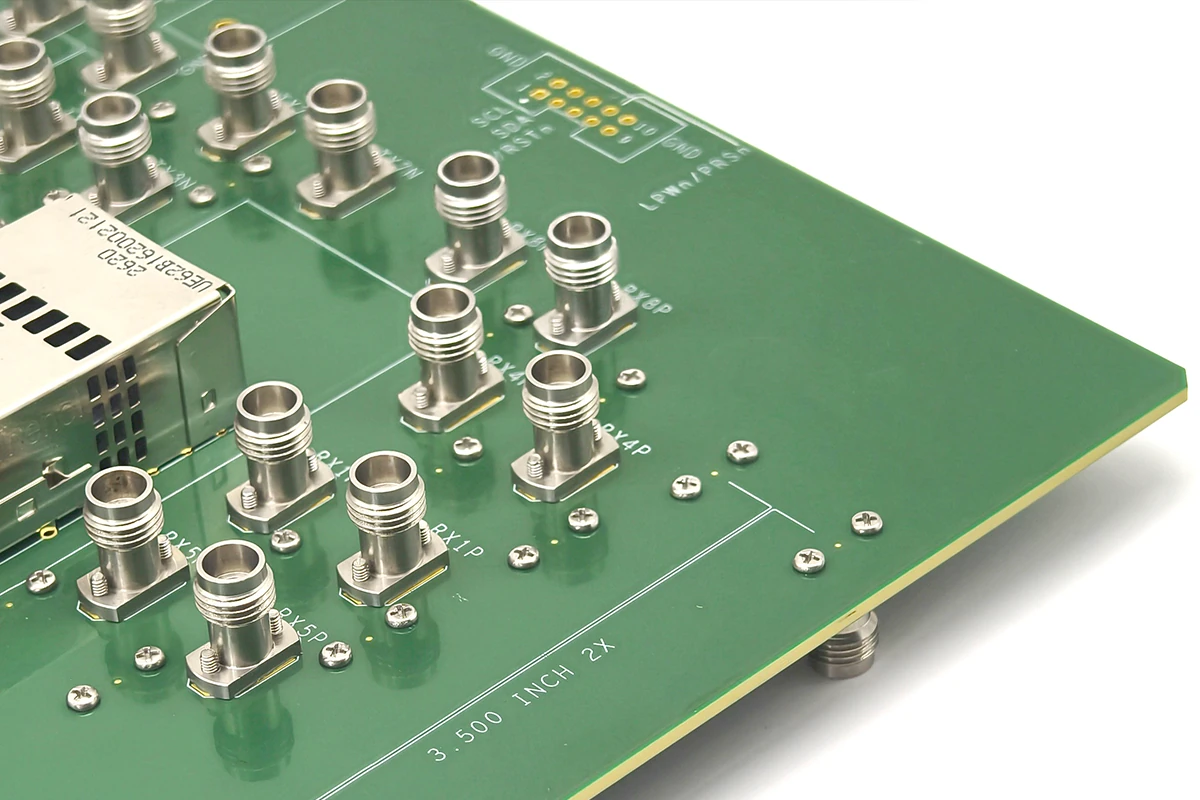
Manufacturing Tolerance Is Part of the Stack-Up
An RF launch is fabricated, not just simulated.
Actual PCBs include tolerances in areas such as:
- dielectric thickness;
- drill location;
- finished via geometry;
- internal-layer registration;
- copper-feature dimensions.
For wideband via transitions, relative alignment between the signal via, anti-pad, internal trace, and surrounding ground structure can affect the realized launch.
That means a launch should not only perform at nominal CAD dimensions.
It should also be practical for the selected PCB fabrication process.
For demanding designs, 3D full-wave electromagnetic simulation can be used to evaluate the actual connector-to-PCB transition before hardware is released.
Physical validation may then use a test coupon, S-parameter measurement, or fixture characterization depending on the application.
The objective is not to simulate every PCB connector by default.
It is to use simulation and measurement where the bandwidth, stack-up complexity, and cost of a PCB respin justify the effort.
Engineering Checklist Before Releasing the PCB
Before transferring or releasing a solderless vertical launch design on a new PCB, review:
-
Required measurement bandwidth
What bandwidth must the complete connector-to-PCB transition support? -
Connector interface and mechanical limits
Is the PCB thickness and mounting arrangement compatible with the selected connector? -
Actual PCB stack-up
What materials, dielectric spacing, routing layers, and PCB ground/reference planes define the launch region? -
Routing architecture
Is the signal leaving through top-layer microstrip/GCPW or transitioning to an internal layer? -
Local transmission-line geometry
Does the new board preserve the line and reference geometry assumed by the reference launch? -
Vertical transition, where applicable
Has the signal via, plane clearance, ground structure, and unused via section been reviewed for the target routing layer? -
PCB fabrication capability
Can the fabricator reliably control the dimensions and registration required by the launch? -
Validation method
Is the design close enough to a proven reference, or does the new construction justify EM simulation or measurement?
The final question is simple:
Is this still the same RF launch electrically—or does it only look similar mechanically?
The Connector and PCB Construction Define the Launch Together
Selecting the correct solderless vertical launch connector requires more than matching a connector to an overall PCB thickness.
Mechanical compatibility determines whether the connector can be installed correctly.
The actual PCB stack-up determines the electrical environment into which that connector must transition.
That is why:
Mechanical board-thickness compatibility does not automatically guarantee an optimized RF launch.
Same total PCB thickness does not mean the same RF transition.
And:
A reference launch becomes less transferable as the actual PCB moves away from the stack-up, routing structure, and fabrication assumptions behind that reference design.
Ultimately:
The correct launch is defined by the connector and the actual PCB construction together—not by either one in isolation.
For available Vinstronics 1.0 mm, 1.85 mm, 2.4 mm, and 2.92 mm configurations, see the
Solderless Vertical Launch PCB Connectors
platform.
Discuss Your PCB Stack-Up and Launch Requirements
If you are integrating a solderless vertical launch connector into a new RF or high-speed test fixture, useful information for an engineering review includes:
- target measurement bandwidth;
- connector interface;
- total PCB thickness;
- PCB stack-up;
- dielectric material;
- top-layer or internal-layer routing;
- target routing layer;
- transmission-line structure;
- mounting constraints;
- PCB fabrication limits.
This allows the connector and PCB launch to be evaluated as one interface rather than as two independent parts.

