
Low Loss Cable
Low-loss 50Ω cable family for attenuation-sensitive RF and microwave transmission paths.
Designed for broadband microwave transmission, high-frequency interconnects, and applications where engineers need to balance attenuation, cable diameter, frequency range, temperature capability, and installation envelope when standard flexible cable no longer provides enough signal margin.
What is Low Loss Cable?
A 50Ω coaxial cable family selected when attenuation reduction becomes a primary design requirement. It is commonly used in RF and microwave systems where higher frequency, longer path length, or tighter loss margin make lower-loss transmission more important than using a smaller general-purpose cable.
The Engineering Value
As operating frequency and routed length increase, cable attenuation consumes more of the RF budget. This family gives engineers a more effective way to reduce loss while balancing diameter, bend planning, temperature range, and system packaging constraints.
Why Choose This Family?
Lower Attenuation for Demanding RF Runs
A practical choice when operating frequency and routed length make transmission loss harder to ignore.
Broader Platform Range
Provides multiple diameter platforms to balance the loss budget against available space, routing radius, and system packaging.
Lower Loss Without Moving to Semi-Rigid
Intended for applications that need lower attenuation than standard flexible cable while keeping installation practical.
Assembly-Ready Configurations
Suitable for raw cable screening or custom-terminated assemblies with selected RF interfaces and defined routing needs.
Model Performance Overview
Screen the family by attenuation curve, platform size, bend planning, frequency capability, and temperature range before moving into detailed model selection.
Reference Attenuation Comparison
Published cable attenuation (dB/100m) across representative frequencies.
Better when routing space is limited and frequency ceiling matters more than achieving the lowest attenuation in the family.
- Representative models: L23, L37
- Usually chosen for: shorter runs, denser layouts, compact microwave interconnects
Better when the design needs a practical compromise between attenuation, bend radius, frequency coverage, and installation space.
- Representative models: L52, L52S, L53, L53S, L63
- Usually chosen for: subsystem interconnects, cabinet transmission paths, general broadband RF routing
Better when route length or attenuation budget leaves limited system margin and lower loss matters more than cable size.
- Representative models: L87, L94
- Usually chosen for: longer RF paths, larger enclosures, lower-loss transmission runs
Recommended Decision Table
Structural and electrical reference parameters for low loss model screening.
| Model | OD (mm) | Operating Freq. | Cut-off Freq. | Attenuation @ 1 GHz | Attenuation @ 10 GHz | Velocity (Vp) | Static Bend Radius | Temp Range |
|---|---|---|---|---|---|---|---|---|
| L23 | 2.33 | 40 GHz | 71 GHz | 70.1 dB/100m | 229.9 dB/100m | 76% | 11 mm | -55 ~ +165°C |
| L37 | 3.75 | 40 GHz | 40 GHz | 39.4 dB/100m | 127.9 dB/100m | 76% | 19 mm | -55 ~ +165°C |
| L52 | 5.20 | 26.5 GHz | 28 GHz | 25.0 dB/100m | 83.0 dB/100m | 76% | 26 mm | -55 ~ +165°C |
| L52S | 5.30 | 26.5 GHz | 28 GHz | 30.6 dB/100m | 100.7 dB/100m | 76% | 26 mm | -55 ~ +165°C |
| L53 | 5.30 | 18 GHz | 25 GHz | 25.3 dB/100m | 82.1 dB/100m | 76% | 26 mm | -55 ~ +165°C |
| L53S | 5.30 | 18 GHz | 25 GHz | 30.4 dB/100m | 102.2 dB/100m | 76% | 26 mm | -55 ~ +165°C |
| L63 | 6.35 | 18 GHz | 23 GHz | 21.4 dB/100m | 71.8 dB/100m | 76% | 31 mm | -55 ~ +165°C |
| L87 | 8.70 | 10 GHz | 14 GHz | 12.6 dB/100m | 43.8 dB/100m | 76% | 46 mm | -55 ~ +165°C |
| L94 | 9.40 | 10 GHz | 13 GHz | 14.2 dB/100m | 48.0 dB/100m | 76% | 50 mm | -55 ~ +165°C |
Note: S-designated variants should be reviewed against published model data for exact attenuation and construction differences. Raw cable frequency limits and final usable assembly frequency are not the same, and should be evaluated together with the selected connector interface.
Representative Assemblies
Three typical directions for turning the low loss family into a finished RF or microwave assembly.
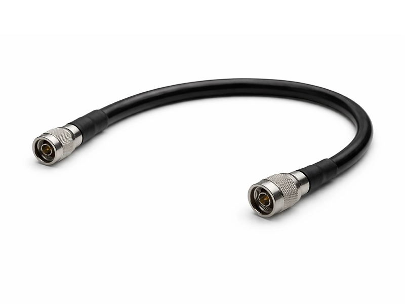
Low-Loss RF Transmission Assembly
For RF and microwave paths where attenuation accumulates over distance and a larger installation envelope is acceptable.
- Best fit Longer RF transmission paths
- Priority Lower attenuation
- Typical interface N-Type, TNC
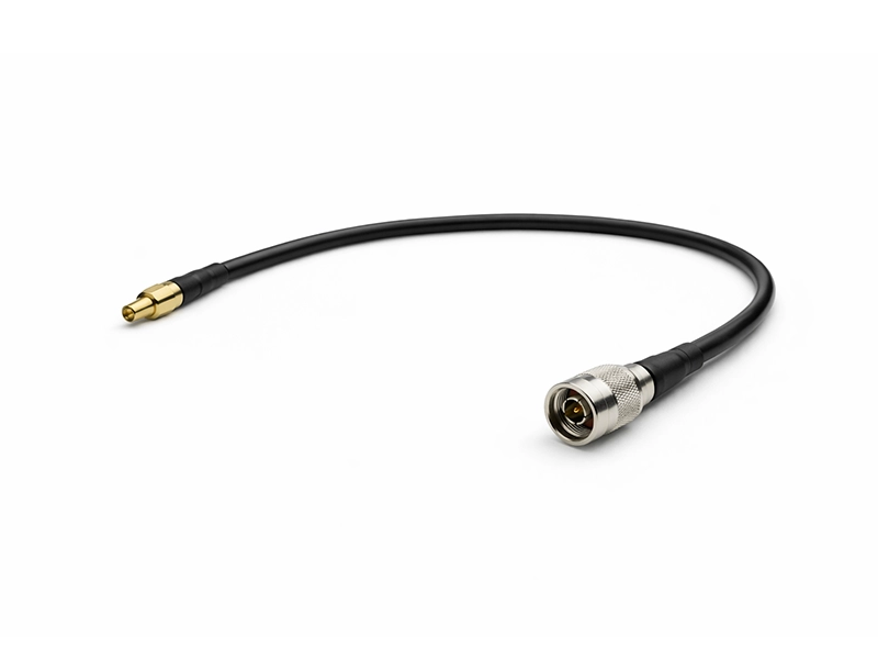
Broadband System Interconnect
For microwave and RF system interconnects where attenuation, diameter, and installation practicality must be balanced together.
- Best fit Cabinet & subsystem transmission
- Priority Loss vs size balance
- Typical interface SMA, 3.5mm, N-Type
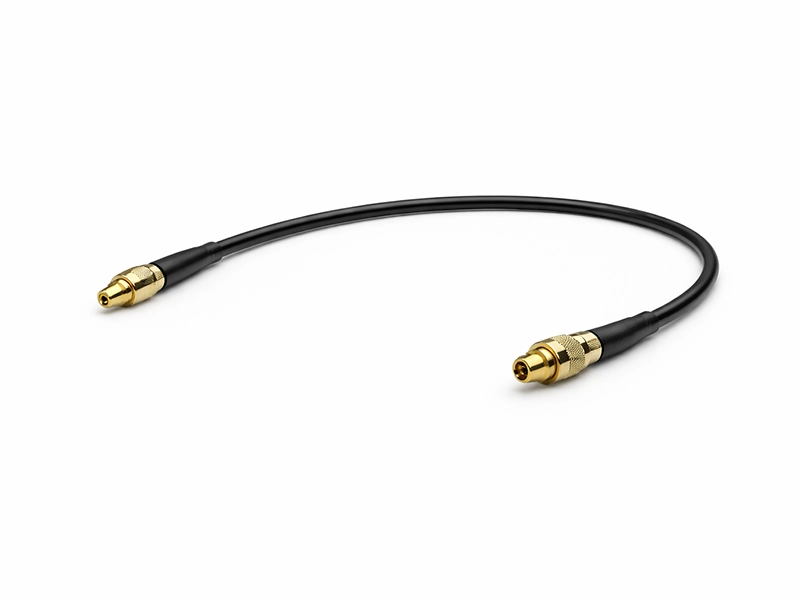
Low-Loss Microwave Test Assembly
For test, validation, and ATE paths where lower loss is needed across higher-frequency measurement paths.
- Best fit Test & validation paths
- Priority Lower transmission loss
- Typical interface Precision SMA, 2.92mm
Typical Applications
Broadband Test & Measurement
Measurement and validation paths where insertion loss must be controlled across wide frequency sweeps.
Wireless Infrastructure
Internal interconnect and jumper paths inside base station equipment where lower attenuation and manageable bend radius are both required.
Radar & Defense Subsystems
Microwave interconnects inside shelters, cabinets, and equipment racks where lower transmission loss supports system margin.
Avionics & RF Equipment Integration
Installed transmission paths where cable size, temperature capability, and low attenuation must be evaluated together.
Key Technical Considerations
Insertion Loss vs. Cable Attenuation
Cable attenuation is a raw property. Final insertion loss also includes connector mismatch and assembly effects, so termination quality matters in the finished result.
The Size Trade-off
Lower loss generally points toward a larger platform, but that also increases bend radius and installation space. The right answer is the best overall fit, not simply the largest cable.
Temperature & Platform Selection
Low loss model selection should also account for operating temperature range, installation environment, and how those constraints affect material choice and long-term reliability.
Low PIM Feasibility
Certain configurations may support low PIM requirements, but this depends on connector choice, assembly process, and finished assembly validation rather than cable construction alone.
Related Flexible Cable Families
Explore adjacent flexible cable families built around different engineering priorities.
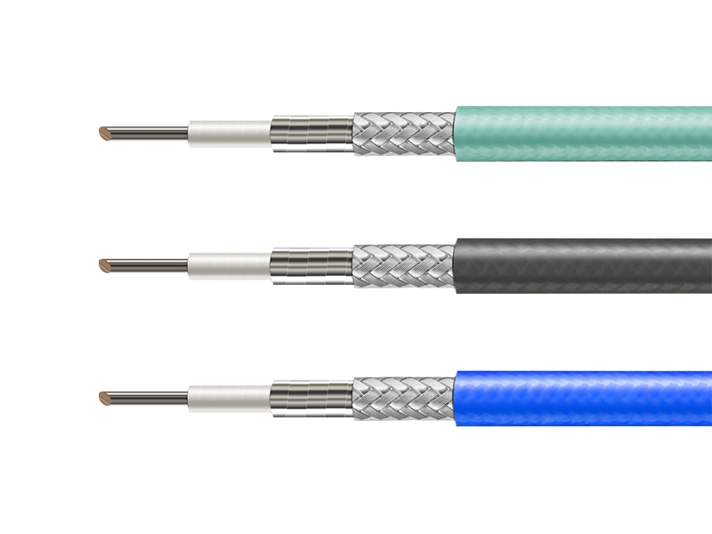
Phase-Stable Flexible Cable
For applications where phase consistency is the dominant engineering filter rather than minimum attenuation.
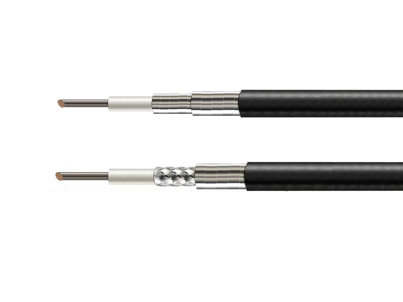
Flexible Low Loss Cable
For applications that still need low attenuation, but place greater priority on cable softness and easier routing flexibility.

High Power RF Cable
For transmitter and higher-power paths where power handling and thermal behavior dominate model selection.
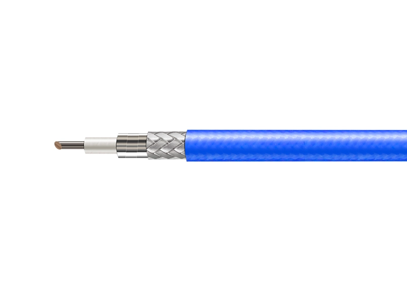
General Purpose Flexible Cable
For cost-conscious RF routing where standard flexible cable performance is sufficient and lower attenuation is not the primary filter.
Low Loss Cable FAQ
What defines a low loss RF cable?
It uses a construction intended to reduce signal attenuation over distance in RF and microwave transmission systems.
How should I estimate whether a larger low loss platform is necessary?
Review operating frequency, path length, and allowable attenuation. If the projected cable loss consumes too much margin, a larger platform may be required.
How is low loss cable different from phase-stable cable?
Low loss cable is chosen mainly to reduce attenuation. Phase-stable cable is chosen mainly to control electrical phase behavior under bending or temperature change.
How is low loss cable different from high power cable?
Low loss cable is screened mainly by attenuation and installation tradeoffs. High-power cable is screened mainly by power handling and thermal behavior.
How do I choose between low loss cable and flexible low loss cable?
Choose low loss cable when attenuation, broader microwave capability, and temperature range are the main priorities. Choose flexible low loss cable when lower attenuation still matters, but softer cable handling and easier routing are more important.
Does low loss automatically mean low PIM?
No. Low PIM depends heavily on connector selection, assembly process, and finished assembly validation.
Can Vinstronics provide terminated low loss cable assemblies?
Yes. We support low loss cable assemblies with selected interfaces, defined lengths, and routing-oriented configuration support.
Low Loss Cable Specification Guide
Download the technical datasheet for model capability comparison and reference parameters.
Discuss Your Low Loss Requirement
Our engineering team can help narrow the right low loss platform for your system, including attenuation tradeoffs, cable size screening, bend planning, connector selection, and custom assembly definition.
- • Operating frequency range
- • Approximate cable length
- • Allowable attenuation or signal budget target
- • Bend or installation constraints
- • Connector requirement