
High Power RF Cable
Flexible 50Ω cable family for transmitter feeds, microwave system routing, and custom RF cable assemblies.
Designed for RF systems where continuous-wave power handling, attenuation, installation space, and routed interconnect practicality must be balanced together. For projects where low PIM is a design priority, selected configurations can be reviewed at the assembly level.
What is High Power RF Cable?
A flexible 50Ω coaxial cable family intended for applications where average RF power capability is materially important. It is typically selected when engineers need to balance power handling, attenuation, cable size, and routing practicality rather than optimize for only one parameter.
The Engineering Value
In many real systems, the cable decision is not just about maximum frequency. It is about whether the interconnect can support the required power path with a workable loss profile and a realistic installation envelope. This family is positioned for exactly that kind of engineering decision.
Why Choose This Family?
Power-Oriented Platform Selection
A practical starting point when the cable sits in a transmitter feed, high-power RF path, or other installation where average power capability meaningfully affects design margin.
Lower-Loss, Larger-Format Options
Larger cable platforms can help reduce attenuation and support stronger power handling, while smaller platforms remain easier to route. This family lets engineers compare those tradeoffs more clearly.
Support for Low-PIM-Oriented Requirements
For infrastructure and other PIM-sensitive use cases, configuration and assembly discussions can be aligned to low-PIM priorities where required.
Bulk Cable or Terminated Assembly
Suitable for projects that begin with raw cable screening and then progress into a defined high-power assembly with selected interfaces, target length, and routing intent.
Model Performance Overview
A faster way to compare the family using two primary screening metrics: average CW power and attenuation at published reference frequencies.
Reference CW Power Comparison
Average continuous-wave power (W) plotted from the published series data.
Reference Attenuation Comparison
Insertion loss (dB/100m) plotted from the published series data.
How to read this section: Larger cable platforms usually provide higher average power capability and lower attenuation, but they also require more routing space and larger bend radius. Smaller platforms preserve a more compact installation envelope and often extend to higher raw-cable cut-off frequencies, but with lower power capacity.
Recommended Decision Table
Structural and electrical reference parameters for representative high-power series models.
| Model | OD (mm) | Operating Freq. | Cut-off Freq. | CW Power @ 1 GHz | CW Power @ 10 GHz | Attenuation @ 10 GHz | Static Bend Radius |
|---|---|---|---|---|---|---|---|
| B46 | 4.60 | 18 GHz | 35 GHz | 569 W | 174 W | 116.0 dB/100m | 23 mm |
| B52 | 5.20 | 18 GHz | 28 GHz | 750 W | 227 W | 91.5 dB/100m | 26 mm |
| B55 | 5.45 | 18 GHz | 28 GHz | 810 W | 244 W | 87.3 dB/100m | 22 mm |
| B63 | 6.35 | 18 GHz | 27 GHz | 1,020 W | 305 W | 74.2 dB/100m | 31 mm |
| B76 | 7.62 | 18 GHz | 19 GHz | 1,530 W | 464 W | 59.5 dB/100m | 38 mm |
| B93 | 9.30 | 10 GHz | 15 GHz | 1,839 W | 534 W | 50.6 dB/100m | 51 mm |
| B120 | 12.00 | 10 GHz | 11 GHz | 2,590 W | 745 W | 45.2 dB/100m | 60 mm |
| B147 | 14.70 | 6 GHz | 8 GHz | 4,080 W | 1,537 W (@ 6 GHz) | 27.1 dB/100m (@ 6 GHz) | 76 mm |
For low-PIM-oriented projects, final passive intermodulation performance should be reviewed at the finished assembly level, together with connector choice, assembly process, and test condition.
Raw-cable cut-off frequency and final usable assembly frequency are not the same. Connector configuration should always be checked together with the cable platform.
Note: B147 reference values shown at 6 GHz reflect its listed operating limit.
Representative Assemblies
Typical high-power cable assembly directions for transmitter, infrastructure, and system-level routing requirements.
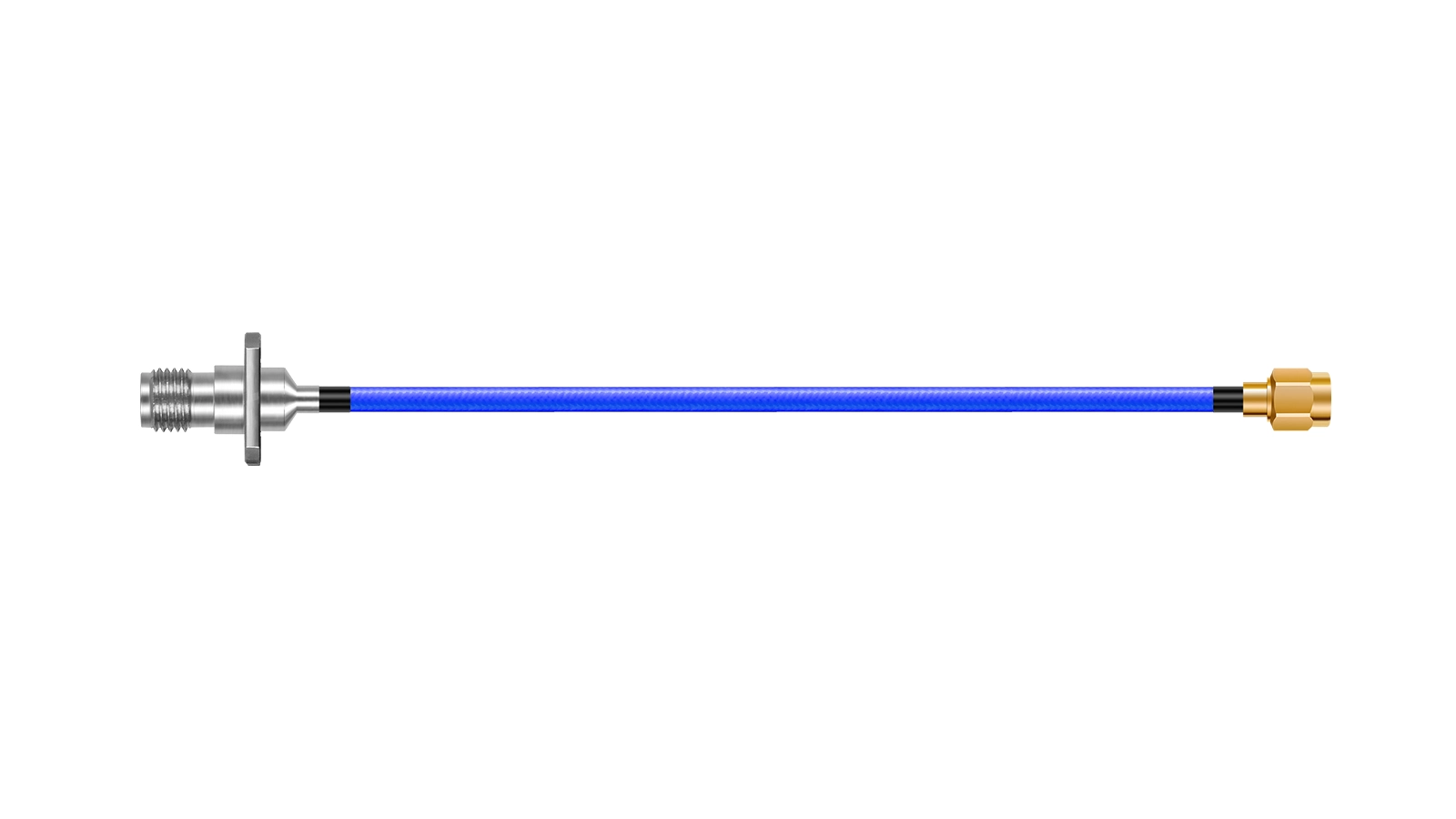
High-Power Transmitter Feed Assembly
Configured for transmitter and other power-capable RF paths where attenuation, cable size, and routing practicality must be balanced at the assembly level.
- Primary Use Transmitter Feed
- Design Focus Power + Loss Balance
- Assembly Scope Cable + Interface Selection
- Typical Fit Power-Capable RF Routing
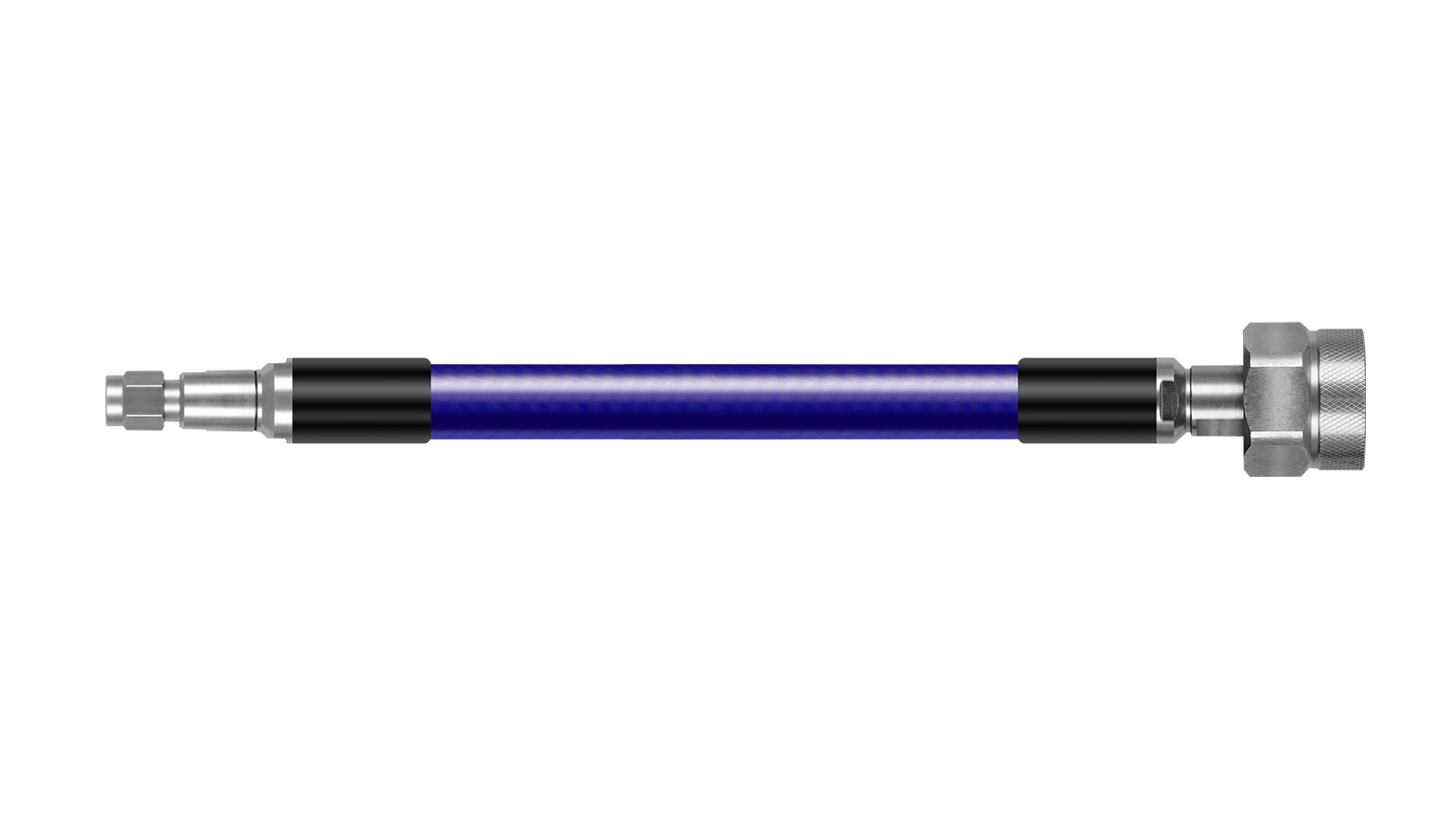
Low-PIM Infrastructure Jumper
Built for wireless infrastructure and related interconnect paths where low-PIM-oriented assembly design is an important requirement alongside power handling.
- Primary Use Infrastructure Interconnect
- Design Focus Low PIM + Power Path
- Assembly Scope Configuration Dependent
- Typical Fit PIM-Sensitive Systems
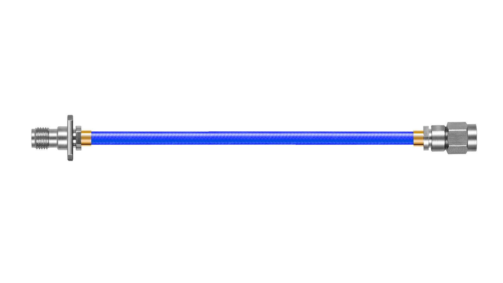
Custom High-Power System Interconnect
Intended for projects that require selected interfaces, controlled length, and installation-oriented routing support across cabinets, racks, and subsystem assemblies.
- Primary Use System Interconnect
- Design Focus Routing + Integration
- Assembly Scope Custom Configuration
- Typical Fit Rack / Cabinet / Subsystem
Typical Applications
High-Power Transmitter Feeds
For routed RF paths where continuous-wave power capability, cable size, and attenuation all affect the workable design choice.
Radar & Microwave System Routing
For system interconnects that need a practical balance between microwave performance, power delivery, and installation constraints.
Wireless Infrastructure Interconnects
For assembly discussions where RF power and low-PIM priorities may both matter within the final interconnect path.
Custom High-Power Test & System Leads
For engineering and validation environments where the finished cable assembly must align with a defined frequency, power, and routing condition.
Key Technical Considerations
Thermal Margin & CW Power
High-power transmission places real thermal stress on the cable path. The practical selection should account for operating frequency, average power, cable length, and the actual installation environment rather than relying on a single headline value.
Low PIM is Usually Assembly-Specific
In PIM-sensitive systems, performance depends not only on the cable platform but also on connector selection, assembly process, and test condition. Requirements should therefore be reviewed at the finished assembly level.
Routing Space vs. Power Capability
Higher power handling often points toward a larger cable construction, but that also increases bend radius and the space required inside the system. The right answer is usually the best overall fit, not simply the largest cable.
Connector Choice Can Limit the Assembly
The finished assembly performance is influenced by the selected interface as well as the cable itself. Frequency range, power target, and mechanical packaging should be reviewed together before locking the final build.
Related Flexible Cable Families
If high power is not your only filter, explore adjacent cable families optimized for different routing priorities.
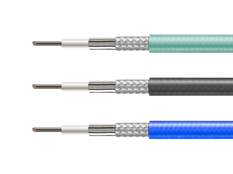
Phase-Stable Flexible Cable
For VNA metrology, phase tracking, and routed interconnects where electrical repeatability is the dominant filter.
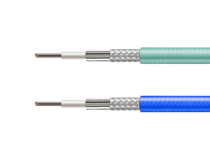
Low-Loss Flexible Cable
For attenuation-sensitive broadband routing where insertion loss is the primary engineering filter.

Ultra-Flexible RF Cable
For tighter bend routing, denser layouts, and installations where mechanical flexibility is prioritized over power capacity.
High Power RF Cable FAQ
What defines a high power RF cable?
It is a cable family selected for RF paths where average power handling is important and where attenuation, size, and routing constraints must still remain practical.
How should I screen the right model first?
Start with frequency range, average power, cable length, routing space, and bend constraint. Then compare attenuation and cable diameter together rather than looking at one value in isolation.
Does larger cable diameter always mean higher power handling?
In general, larger platforms can support stronger power handling and lower attenuation, but they also demand more routing space and a larger bend radius. Final selection should still reflect the full system condition.
How does CW power change with frequency?
Average power capability generally decreases as operating frequency increases. Published power data should always be checked at the actual working band, not only at a single reference point such as 1 GHz.
Can low-PIM requirements be supported?
Yes. For PIM-sensitive projects, Vinstronics can support low-PIM-oriented configuration and assembly discussions. Final PIM performance should be confirmed at the finished assembly level.
What should I provide for a faster recommendation?
Provide your working frequency range, average CW power, cable length, connector type, bend constraint, installation space, and whether your requirement is for bulk cable or a completed assembly.
High Power RF Cable Specification Guide
Download the technical PDF for representative model comparison and reference parameters.
Discuss Your High Power Routing Requirement
Our engineering team can help narrow the right cable platform for your system, including power-versus-loss tradeoffs, cable size screening, connector selection, bend planning, and custom high-power cable assembly definition.
Typical inputs: frequency range, average CW power, cable length, bend constraint, connector type
- • Operating frequency range
- • Average CW power or system power target
- • Approximate cable length
- • Bend or installation constraints
- • Connector requirement
- • Bulk cable or finished assembly