
Choosing between SMA, 3.5mm, 2.92mm, 2.4mm and 1.85mm RF connectors is not only a catalog comparison. The connector choice affects usable frequency range, mating safety, calibration repeatability, cable assembly performance, PCB launch behavior and long-term interface reliability.
At lower frequencies, the decision may be driven by availability, cost and mechanical fit. At higher frequencies, a connector that appears physically compatible can still be the wrong choice for a microwave test port, precision cable assembly, solderless PCB launch or mmWave measurement path.
Engineer’s Selection Problem
The real decision is not whether the connector can be threaded onto the mating part. It is whether the interface gives enough frequency margin, protects the measurement chain, avoids accidental mismating and still fits the mechanical constraints of the cable assembly, PCB launch, module or instrument port.
Short answer: Use SMA connectors for general RF applications where the frequency range and interface quality are clear. Use 3.5mm connectors when rugged precision microwave mating and lab repeatability matter. Use 2.92mm connectors for 40 GHz-class high-frequency paths. Use 2.4mm connectors when a 50 GHz-class controlled chain is required. Use 1.85mm connectors when the application needs 67 GHz-class precision performance.
This guide compares SMA, 3.5mm, 2.92mm, 2.4mm and 1.85mm connector families from an engineering selection perspective. It also explains how the connector choice affects RF cable assemblies, PCB launch designs and high-frequency test setups.
Why These RF Connector Families Are Often Compared
SMA, 3.5mm, 2.92mm, 2.4mm and 1.85mm connectors are often discussed together because they appear in many of the same RF and microwave systems: signal generators, VNAs, adapters, test cables, PCB launch connectors, coaxial assemblies and microwave modules.
The difficulty is that some of these connector families are mechanically related or used in adjacent frequency ranges, but they should not be treated as identical. Mechanical fit, frequency rating, interface condition, dielectric support, torque practice and the full interconnect chain all matter.
For engineering teams, the practical question is not only “which connector fits?” but “which connector preserves the measurement or system performance margin without unnecessary cost or compatibility risk?”
Quick Comparison Table
| Interface | Common frequency class | Typical role | Selection note |
|---|---|---|---|
| SMA | Commonly used through 18 GHz, depending on design and grade | General RF systems, antennas, standard cable assemblies and production hardware | Practical and widely available when frequency margin and interface quality are clear. |
| 3.5mm | Precision microwave class, commonly associated with 26.5 GHz to 34 GHz-class use depending on design | Lab test, calibration hardware and rugged precision microwave interfaces | Useful where mechanical durability and precision mating behavior are important. |
| 2.92mm / K | 40 GHz class | High-frequency test cables, PCB launch connectors and microwave modules | A common choice when SMA margin is not enough for microwave measurement paths. |
| 2.4mm | 50 GHz class | Higher-frequency precision test systems, adapters and cable assemblies | Use when the full interconnect chain is controlled for higher-frequency work. |
| 1.85mm / V | 67 GHz class | Precision measurement, mmWave test and high-frequency cable assemblies | Use when performance above the 50 GHz class is required. |

Frequency Range and Interface Selection
Frequency range is usually the first filter, but it should not be the only selection factor. The final connector choice should also consider cable type, adapter chain, PCB launch, mating cycles, calibration method and whether the connector will be used in a finished cable assembly or a fixed module interface.
For many systems, SMA is a practical and cost-effective solution. When the frequency rises or measurement repeatability becomes more important, engineers often move toward 3.5mm, 2.92mm, 2.4mm or 1.85mm connector families.
Engineering note: Do not select a connector only by its maximum advertised frequency. The weakest part of the path may be the cable, adapter, PCB launch, mating condition or assembly process.
For finished cable assemblies, connector selection should be reviewed together with insertion loss, return loss and VSWR, and whether S-parameter test data is required.
When to Choose SMA Connectors
SMA connectors remain one of the most widely used RF connector families. They are common in RF modules, antennas, test fixtures, lower-frequency cable assemblies, production systems and general RF equipment.

Choose SMA when:
- The operating frequency and performance margin fit the specific SMA connector rating.
- Cost, availability and package fit matter more than precision microwave repeatability.
- The connection is used in general RF modules, antennas or low-to-mid-frequency test setups.
- The application does not require a precision interface for repeated high-frequency calibration.
The caution is that not every SMA connector is suitable near the upper end of a microwave test path. Connector geometry, dielectric support, interface quality and assembly control should be checked before using SMA in a higher-frequency application.
When to Choose 3.5mm Connectors
3.5mm connectors are often used in precision microwave test environments where mechanical robustness and repeatable mating behavior matter. They are commonly discussed alongside SMA and 2.92mm because these interface families appear close together in many lab and instrument systems.

Choose 3.5mm when:
- The application needs a rugged precision microwave connector.
- The setup involves calibration hardware, instrument interfaces or repeated lab use.
- Mechanical durability and stable mating behavior are important.
- The frequency requirement remains within the connector and system rating.
Compatibility should not be treated casually. A worn, low-grade or damaged SMA connector can degrade a precision microwave interface and may create repeatability problems.
When to Choose 2.92mm Connectors
2.92mm connectors, also widely known as K connectors, are commonly selected for 40 GHz-class high-frequency interconnects. They are used in test cables, adapters, PCB launch connectors, microwave modules and measurement setups where SMA does not provide enough performance margin.
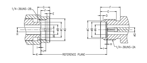
Choose 2.92mm when:
- The design needs a 40 GHz-class precision interface.
- SMA performance margin is not enough for the measurement or signal path.
- The connector will be used in a high-frequency cable assembly, PCB launch, test fixture or microwave module.
- The project requires practical compatibility planning with adjacent SMA or 3.5mm hardware while improving microwave performance margin.
For a focused comparison of 2.92mm and SMA interfaces, see this 2.92mm vs SMA connector selection guide.
When to Choose 2.4mm Connectors
2.4mm connectors are selected for higher-frequency precision microwave work, especially when the connector, adapter, cable and instrument interfaces are specified as a controlled chain. They are not a generic drop-in upgrade for SMA, 3.5mm or 2.92mm hardware.

Choose 2.4mm when:
- The application needs a 50 GHz-class precision interface.
- The test setup uses higher-frequency microwave instrumentation.
- The complete connector, cable, adapter and launch chain can be controlled as a precision system.
- The team can avoid accidental mismating with larger interface families.
For 50 GHz-class systems, the connector decision should be reviewed together with the cable assembly, adapter strategy and instrument port.
When to Choose 1.85mm Connectors
1.85mm connectors, also known as V connectors, are used for 67 GHz-class precision measurement and high-frequency interconnects. They are typically selected when performance above the 50 GHz class is required and the system can support the tighter handling and mating requirements of a smaller precision interface.
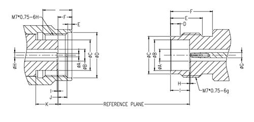
Choose 1.85mm when:
- The application needs 67 GHz-class measurement or interconnect performance.
- The system operates above the practical range of 2.4mm interfaces.
- The cable assembly, adapter and instrument chain are all specified for the required frequency range.
- The project requires precision microwave or mmWave test performance.
Because 1.85mm interfaces are precision components, handling, torque practice, connector cleanliness and adapter selection should be controlled carefully.
Mating Compatibility and Interface Risk
Some RF connector families may appear mechanically related, and some can be used in the same interconnect chain with the correct adapters or compatible interfaces. However, compatibility should not be treated as permission to mix any connector casually.

A damaged SMA connector, incorrect adapter, wrong torque practice or worn test port can create measurement errors or damage a precision microwave interface. Always review the complete interconnect path before mixing connector families.
How to Choose Between 2.92mm, 2.4mm and 1.85mm RF Connectors
For many high-frequency engineers, the real decision is not between SMA and every precision interface. It is between 2.92mm, 2.4mm and 1.85mm after the system moves into higher-frequency microwave work.
| If the application needs… | Start with… | Reason |
|---|---|---|
| A practical 40 GHz-class precision path | 2.92mm | Common choice for high-frequency test cables, PCB launch and microwave modules. |
| More margin above 40 GHz | 2.4mm | Useful for controlled 50 GHz-class measurement chains. |
| 67 GHz-class precision performance | 1.85mm | Selected when the application must operate above the 50 GHz class. |
In practice, the best connector is the one that meets the frequency and repeatability requirement without unnecessary complexity. Over-specifying the connector family can add cost and handling risk. Under-specifying it can reduce measurement margin.
Connector Selection for RF Cable Assemblies
Connector choice affects finished cable assembly performance. A cable assembly should be selected as a complete RF path, not as a connector and cable chosen independently.
When choosing connectors for RF cable assemblies, consider:
- Target frequency range
- Connector family and gender on both ends
- Cable type, loss and flexibility
- Whether the cable is low-loss, phase-stable, semi-rigid or ruggedized
- VNA calibration and test-port compatibility
- VSWR and return loss or insertion loss test requirements
- Expected handling and mating cycles
If the connector will be used in a finished cable assembly, the connector family should be selected together with the cable type, cable length, routing and bend radius, and test data requirement. For RFQ preparation, see this custom RF cable assembly specification checklist.
Connector Selection for PCB Launch and Test Fixtures
For PCB launch, solderless PCB connectors and test fixtures, connector choice depends on more than frequency class. The PCB stackup, launch geometry, ground transition, connector mounting method and available mechanical space can all affect performance.
In high-frequency PCB applications, 2.92mm, 2.4mm and 1.85mm interfaces may be considered depending on the required frequency and board design. For fast prototyping or repeated test use, solderless PCB connectors may also be reviewed when the application supports that structure.
For PCB launch review, provide the operating frequency, connector orientation, board thickness, launch geometry and available space around the connector. For related interface planning, see this end launch vs vertical launch RF connector selection guide.
Selection by Application
| Application | Better connector direction | Reason |
|---|---|---|
| General RF cable assembly | SMA / 3.5mm / 2.92mm | Depends on frequency, cost target and measurement margin. |
| 40 GHz test path | 2.92mm | Common precision interface for 40 GHz-class systems. |
| 50 GHz test path | 2.4mm | Adds margin above 40 GHz when the full chain is controlled. |
| 67 GHz test path | 1.85mm | Supports higher-frequency precision measurement. |
| PCB launch testing | 2.92mm / 2.4mm / 1.85mm | Depends on PCB design, launch structure and frequency. |
| VNA test cable assembly | 2.92mm / 2.4mm / 1.85mm | Interface should match calibration and measurement range. |
Common Selection Mistakes
| Mistake | Why it matters | Better approach |
|---|---|---|
| Choosing SMA because it physically fits | Mechanical fit does not confirm high-frequency margin. | Check rating, launch design and the full RF path. |
| Treating compatibility as full interchangeability | Compatible-looking interfaces can still degrade measurement quality. | Check interface condition, torque practice, rating and application. |
| Selecting only by maximum frequency | Cable, adapter or PCB launch may be weaker than the connector. | Review the complete connector, cable, adapter and launch chain. |
| Using 2.4mm as a generic upgrade | 2.4mm requires controlled mating and adapter planning. | Confirm instrument ports, adapters and handling practice first. |
| Ignoring the cable assembly application | Connector choice affects finished assembly performance and test repeatability. | Select connector and cable type together. |
What to Send for Connector Review
For a new RF connector, cable assembly, PCB launch or adapter-chain decision, engineering review is more useful when the application details are clear.
Useful information includes:
- Target frequency range
- Connector family and gender
- Application: cable assembly, PCB launch, adapter, module or test port
- Cable type or PCB stackup if applicable
- Available mechanical space
- Mating interface and expected mating cycles
- Whether test data, drawings or S-parameter files are required
For connector-family support, review Vinstronics precision RF connectors. For cable assembly selection, start from the RF Cable Assemblies Guide. Connector options include 2.92mm RF connectors, 2.4mm RF connectors and 1.85mm RF connectors.
FAQ
What is the main difference between SMA, 3.5mm, 2.92mm, 2.4mm and 1.85mm connectors?
The main differences are frequency class, mechanical interface, mating compatibility, precision level and application fit. SMA is widely used for general RF applications, while 2.92mm, 2.4mm and 1.85mm are selected for higher-frequency precision paths.
When should I use 2.92mm instead of SMA?
Use 2.92mm when the application needs a 40 GHz-class precision interface, especially in high-frequency test cables, PCB launch connectors, microwave modules or VNA test setups where SMA does not provide enough margin.
Is 2.92mm the same as K connector?
In many RF and microwave contexts, 2.92mm connectors are also referred to as K connectors. Always check the manufacturer drawing, rating and interface condition before mating.
Can 2.4mm connectors mate with 2.92mm connectors?
No. 2.4mm and 2.92mm are different precision interfaces and should not be mated directly. Use the correct adapter strategy and verify the full connector chain.
When should I choose 1.85mm connectors?
Choose 1.85mm connectors when the application requires 67 GHz-class precision performance and the full cable, adapter and instrument chain is specified for that frequency range.
Should I always choose the highest-frequency connector?
No. Higher-frequency connector families can require stricter handling, adapters and assembly control. The best choice is the connector that meets the frequency, repeatability, mechanical and application-fit requirements without unnecessary complexity.
Need help selecting a precision RF connector?
Send your target frequency, connector application, cable assembly requirement, PCB launch condition or instrument-port constraint for engineering review.

