
Engineering problem:
Once the DUT has been confirmed as a suitable SS landing structure, the next decision is whether the measurement requires a 40 GHz or 67 GHz probe platform. The two Vinstronics series use the same Signal-Signal (SS) contact topology, but they are designed for different frequency ranges and RF interface requirements.
The VST-D40G-SS-XXX supports DC–40 GHz with 2.92 mm female interfaces. The VST-D67G-SS-XXX supports DC–67 GHz with 1.85 mm female interfaces. Both are 100 Ω differential SS probes intended for direct board-level PCB and PCBA measurement.
Select a platform that covers the required measurement bandwidth with appropriate margin, without adding unnecessary interface complexity.
The 67 GHz version is not automatically the better choice, and the 40 GHz version is not a lower-quality alternative. The correct platform depends on the measurement objective and the complete RF path.
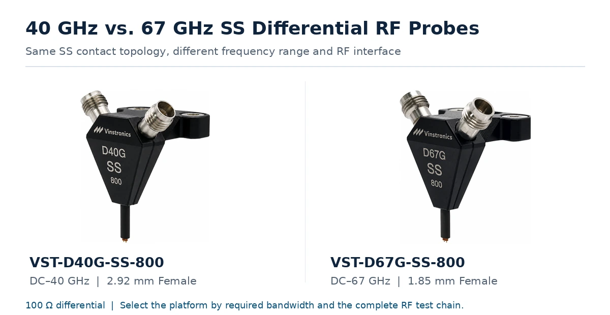
Quick Decision Matrix
| Decision Question | Choose 40 GHz | Choose 67 GHz |
|---|---|---|
| Required upper frequency | Required measurement bandwidth is ≤40 GHz | Required measurement bandwidth extends above 40 GHz, up to 67 GHz |
| VNA capability | 40 GHz system | 67 GHz system |
| Existing RF interface | 2.92 mm cables and accessories | Qualified 1.85 mm test chain |
| Cable and adapter bandwidth | Qualified to the required range up to 40 GHz | Qualified through the required upper band |
| Measurement objective | Required characterization is fully contained below 40 GHz | Required insertion loss, return loss, or mixed-mode characterization extends above 40 GHz |
What the Two Platforms Have in Common
The VST-D40G-SS-XXX and VST-D67G-SS-XXX use the same SS contact topology and 100 Ω differential configuration.
- Signal-Signal contact configuration
- 100 Ω differential impedance
- Pitch configurations for PCB-level differential pads
- 45-degree RF connector arrangement
- 5 g contact force
- Direct PCB and PCBA differential measurement capability
The platform supports pitch configurations within the published 350–3000 µm range. An individual probe is supplied for the defined DUT pad pitch; the range does not mean one probe is continuously adjustable across every spacing.
This article assumes that the SS landing structure and required pitch have already been confirmed. For those earlier decisions, see SS vs. GSSG RF Probes for Differential PCB Testing and How to Specify an SS RF Probe from PCB Pad Geometry.
The Main Difference: Required Measurement Bandwidth
The first question is not “Which probe has the higher specification?” It is:
VST-D40G-SS-XXX
The 40 GHz platform is intended for measurements from DC to 40 GHz and uses 2.92 mm female interfaces.
It is the logical starting point when:
- The required measurement range remains within 40 GHz
- The VNA is a 40 GHz-class instrument
- The existing test cables and accessories use 2.92 mm interfaces
- The DUT launch and fixture are not intended for characterization above 40 GHz
- No required characterization extends above 40 GHz
VST-D67G-SS-XXX
The 67 GHz platform extends the supported range to DC–67 GHz and uses 1.85 mm female interfaces.
It should be considered when:
- The required differential measurement extends above 40 GHz
- A suitable 67 GHz VNA is available
- The cable, adapter, and connector path supports the required upper band
- The PCB transition is intended for characterization above 40 GHz
- The measurement objective requires data above 40 GHz
The higher maximum frequency rating does not by itself establish lower uncertainty or better accuracy below 40 GHz.
2.92 mm vs. 1.85 mm RF Interfaces
| Platform | Probe Interface | Probe Range |
|---|---|---|
| VST-D40G-SS-XXX | 2.92 mm Female | DC–40 GHz |
| VST-D67G-SS-XXX | 1.85 mm Female | DC–67 GHz |
The connector choice affects the VNA port or test-set interface, cable connector type, adapter path, calibration hardware, mating sequence, and cable routing around the probe positioner.
A laboratory already standardized on 2.92 mm hardware may avoid unnecessary interface changes by selecting the 40 GHz platform when the required bandwidth remains within 40 GHz. A 67 GHz measurement requires the rest of the RF path to support the intended upper frequency.
The Probe Does Not Define the Entire System Bandwidth
The usable measurement bandwidth is limited by the lowest-bandwidth or least-controlled element in this path.
A 67 GHz probe does not create a 67 GHz measurement if:
- The VNA stops at 40 GHz
- A cable has excessive loss or poor match in the upper band
- An adapter is not qualified for the required frequency
- The calibration does not establish the intended reference plane
- The PCB launch becomes the dominant discontinuity above 40 GHz
Probe bandwidth should therefore be selected as part of a complete measurement-system review. For the cable side of the path, see Vinstronics RF cable assemblies.
Appropriate Bandwidth Margin
The selected platform should provide reasonable margin beyond the exact analysis limit, but the margin should serve a defined purpose.
- Avoiding operation directly at the instrument or accessory limit
- Supporting verification beyond the nominal DUT passband
- Allowing comparison between several interconnect designs
- Providing headroom for later revisions of the same platform
Calibration and Reference Plane
Both platforms require a defined calibration and verification plan.
Calibration establishes a corrected VNA reference plane. De-embedding can then be used, where appropriate, to mathematically remove a characterized probe, fixture, or transition network.
The required workflow depends on:
- Desired measurement reference plane
- Probe and pitch configuration
- Available calibration standards
- PCB landing transition
- Required measurement uncertainty
- Whether the probe or fixture contribution must be removed
A stored de-embedding file does not replace VNA calibration. In the upper band, connector, cable, and transition discontinuities become increasingly significant contributors to measurement uncertainty, making reference-plane definition and connection repeatability more important in the upper band.
Three Practical Selection Examples
Example 1 — Existing 40 GHz Measurement System
The laboratory has a 40 GHz VNA, 2.92 mm RF cables, an 800 µm SS pad layout, and no required measurement content above 40 GHz.
Starting point: VST-D40G-SS-800. A 67 GHz probe would not extend the usable bandwidth of the 40 GHz VNA or the existing test chain.
Example 2 — Differential Measurement Required to 60 GHz
The project requires differential S-parameter characterization to 60 GHz and includes a 67 GHz VNA, 1.85 mm RF cables, a compatible calibration workflow, and a PCB launch intended for the upper band.
Starting point: VST-D67G-SS-XXX. The required range exceeds the 40 GHz platform.
Example 3 — 67 GHz Probe with a 40 GHz-Limited Transition
The probe and VNA support 67 GHz, but the fixture or PCB launch is not adequately characterized above approximately 40 GHz.
Required action: Review the PCB transition, adapter path, calibration reference plane, and fixture model before interpreting the upper-band data.
Selection Checklist
- Required upper measurement frequency
- Appropriate bandwidth margin
- VNA frequency range
- VNA and cable connector interfaces
- Cable and adapter bandwidth
- Calibration method and intended reference plane
- DUT launch bandwidth
- Confirmed SS pad pitch
- Probe and cable clearance
- De-embedding or fixture-removal requirement
- Expected test volume
Model Summary
| Parameter | VST-D40G-SS-XXX | VST-D67G-SS-XXX |
|---|---|---|
| Frequency range | DC–40 GHz | DC–67 GHz |
| RF interface | 2.92 mm Female | 1.85 mm Female |
| Contact configuration | SS | SS |
| Differential impedance | 100 Ω | 100 Ω |
| Pitch availability | Configured for DUT layout | Configured for DUT layout |
| Supported platform range | 350–3000 µm | 350–3000 µm |
| Connector angle | 45° | 45° |
| Contact force | 5 g | 5 g |
Conclusion
The 40 GHz and 67 GHz SS probes should not be treated as lower- and higher-tier versions of the same probe. They are two bandwidth platforms designed for different measurement requirements and RF interface environments.
Choose the VST-D40G-SS-XXX when the required analysis remains within 40 GHz, the existing test chain uses 2.92 mm hardware, and no meaningful content above 40 GHz is required.
Choose the VST-D67G-SS-XXX when the required measurement extends beyond 40 GHz and a qualified 1.85 mm and 67 GHz test chain is available.
FAQ
Is the 67 GHz SS probe always more accurate than the 40 GHz version?
No. The higher maximum frequency rating does not by itself establish lower uncertainty or better accuracy below 40 GHz. Measurement quality depends on the VNA, calibration, cables, adapters, probe transition, and DUT.
Can a 67 GHz SS probe be used with a 40 GHz VNA?
The physical connection may be possible with a compatible interface path, but the measurement bandwidth remains limited by the 40 GHz VNA and the rest of the test chain.
What is the main difference between the two platforms?
The VST-D40G-SS-XXX supports DC–40 GHz with 2.92 mm female interfaces. The VST-D67G-SS-XXX supports DC–67 GHz with 1.85 mm female interfaces.
Do the two platforms use the same differential impedance?
Yes. Both are specified as 100 Ω differential SS probe platforms.
Is the pad pitch determined by the frequency platform?
No. Pad pitch defines the physical contact configuration, while the required analysis bandwidth determines the electrical platform.
Does choosing the 67 GHz probe make the complete setup a 67 GHz system?
No. The VNA, cables, adapters, calibration, PCB transition, and DUT must also support the required upper frequency.
Can one probe be adjusted across the complete 350–3000 µm pitch range?
No. The platform supports configurations within that range, but an individual probe is supplied for the specified DUT pad pitch.
Need a 40 GHz or 67 GHz Configuration Review?
Send your required upper frequency, VNA model, cable and connector interfaces, SS pad pitch, and calibration approach. Vinstronics engineers can review the suitable probe platform before quotation.

