
A low-loss RF cable assembly is not automatically a well-matched RF cable assembly.
In many RFQs, the customer specifies the connector type, cable length and frequency range, then asks for a low-loss cable assembly. That information is useful, but it does not fully define the RF path. At higher frequencies, the connector interface, cable-to-connector transition, termination quality and mating condition can also affect how much signal is reflected back toward the source.
This is where return loss and VSWR become important. They help engineers evaluate impedance matching and reflection behavior in the finished cable assembly, not only the loss through the cable body.
Typical RFQ Gap
“Need a 40 GHz low-loss cable assembly, 500 mm, 2.92 mm male to 2.92 mm male.” This is a good start, but it does not define the target VSWR, return loss, test frequency range, mating interface or whether assembly-level test data is required.
Quick engineering distinction: Insertion loss shows how much signal passes through the cable assembly. Return loss and VSWR show how well the assembly is matched and how much signal is reflected because of impedance discontinuities.
Return Loss and VSWR Are Finished-Assembly Measurements
Return loss and VSWR are often discussed as connector or cable specifications, but for a real cable assembly they should be understood at the finished-assembly level. The final result depends on the complete RF path.
A cable assembly includes:
- the coaxial cable structure;
- the connector interface at each end;
- the cable-to-connector transition;
- termination workmanship;
- mating condition with the test port or equipment;
- frequency range and measurement setup;
- routing, bending and strain near the connector area.
This is why two assemblies using similar cable may not show identical return loss if the connector interface, termination method or mating condition is different.
Return Loss vs VSWR vs Insertion Loss
Engineers often review insertion loss first because it is directly related to signal attenuation. But insertion loss does not tell the whole story. A cable assembly can show acceptable insertion loss while still having poor matching at one or more frequency points.
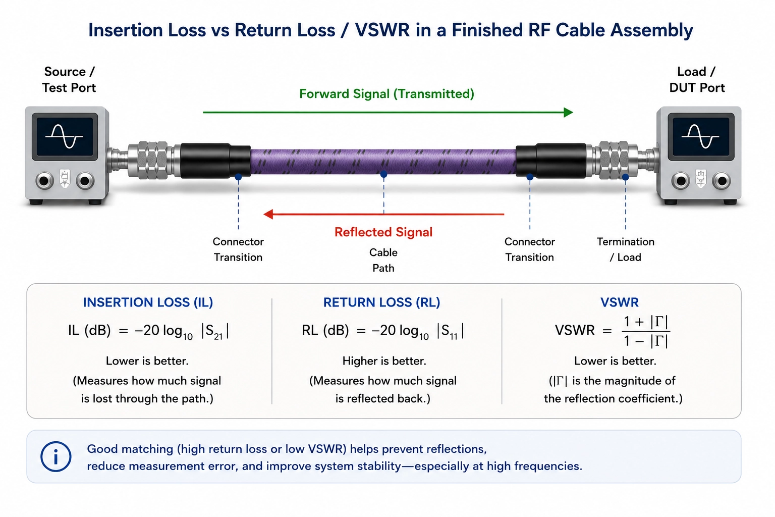
| Parameter | What it indicates | Why it matters in cable assemblies |
|---|---|---|
| Insertion loss | How much signal is lost through the assembly. | Important for loss budget, system gain margin and high-frequency signal path planning. |
| Return loss | How much signal is reflected because of impedance mismatch. | Helps evaluate connector transition quality, interface matching and reflection behavior. |
| VSWR | Another way to express mismatch and reflected energy. | Commonly used in RF specifications, test reports and procurement requirements. |
For the loss-side discussion, see RF Cable Assembly Insertion Loss: What Engineers Should Check Before Ordering. The two topics should be reviewed together when the cable assembly is used in a high-frequency or measurement-sensitive path.
Where Return Loss Problems Usually Come From
Return loss and VSWR issues often come from small discontinuities that become more visible as frequency increases. The problem is not always the cable itself. In many cases, the connector transition or mating condition is the more important factor.
Common sources include:
- Connector interface mismatch: the selected connector may not be suitable for the full operating frequency or mating environment.
- Cable-to-connector transition: poor transition control can create reflection points near the termination.
- Termination workmanship: assembly process consistency affects the finished RF path.
- Mating condition: worn, contaminated, damaged or poorly torqued interfaces may change measured performance.
- Frequency extension: using an interface too close to or beyond its practical range increases risk.
- Mechanical stress near the connector: tight bending or pulling near the termination can affect repeatability.
This is one reason cable assemblies should be specified as complete interconnect paths, not only as cable plus connector part names. For related selection logic, see cable and connector selection for custom RF cable assemblies.
When Typical VSWR Information May Be Enough
Not every RF cable assembly requires full S-parameter data or detailed return loss review. For some applications, typical VSWR information or standard production test limits may be sufficient.
Typical information may be enough when:
- the operating frequency is moderate;
- the cable assembly is used in a non-critical system interconnect;
- the loss and matching requirements are not tight;
- the cable will not be used as part of a calibrated measurement path;
- the customer only needs a general-purpose replacement or internal connection.
In these cases, the RFQ can remain simple, but the frequency range, connector pair and cable length should still be clearly defined.
When Assembly-Level Return Loss or VSWR Test Data Should Be Requested
Assembly-level test data becomes more useful when the cable assembly is part of a critical RF path. This is especially true for high-frequency testing, VNA measurements, production test systems, calibration-related setups and equipment where mismatch can affect the measurement result.
Consider requesting assembly-level data when:
- the assembly is used at high frequency;
- the path has a defined VSWR or return loss requirement;
- the cable is used with a VNA, signal analyzer, signal generator or test fixture;
- the assembly will be used in repeatable lab or production testing;
- the connector interface is close to its practical frequency limit;
- the system has a tight loss or matching budget;
- the cable path includes tight routing or bending near the connector.
For routing-related effects, see RF Cable Assembly Bend Radius: Why Routing Matters at High Frequencies. For length-related planning, see How Cable Length Affects RF Cable Assembly Performance at High Frequencies.
What Engineers Should Specify Before Quotation
To avoid unclear performance expectations, engineers should define the return loss or VSWR requirement before quotation whenever the application is sensitive to matching.
Useful RFQ information includes:
- operating frequency range;
- connector type and gender at both ends;
- mating equipment or test port interface;
- cable length and tolerance requirement;
- target VSWR or return loss, if defined;
- whether insertion loss data is also required;
- whether a PDF test report, data table or Touchstone file is needed;
- routing condition, bend radius or installation constraint;
- quantity and whether the assembly is for prototype, lab test or production use.
For a broader RFQ checklist, see Custom RF Cable Assemblies: What Engineers Need to Specify.
Common Mistakes to Avoid
- Only asking for “low loss” without defining return loss or VSWR requirement.
- Assuming cable datasheet values represent the finished cable assembly.
- Choosing a connector interface based only on availability, not frequency range or mating condition.
- Using an interface too close to its practical limit without requesting test data.
- Ignoring connector wear, torque and cleanliness in high-frequency measurements.
- Comparing assemblies without confirming the same test setup and frequency sweep.
These mistakes can lead to unclear quotation scope or unexpected performance differences during test.
Practical Takeaway
Return loss and VSWR are not just catalog numbers. For high-frequency RF cable assemblies, they reflect the quality of the full interconnect path, including connector interface, transition control, termination workmanship and mating condition.
If the application is sensitive to reflections, define the target VSWR or return loss during the RFQ stage. When needed, request assembly-level test data across the actual operating frequency range. This helps prevent a cable assembly from meeting a general description while missing the real matching requirement.
FAQ
Is return loss the same as VSWR?
No. Return loss and VSWR both describe impedance mismatch and reflected energy, but they use different formats. Many RF specifications use one or the other depending on the application and test convention.
Can a cable assembly have low insertion loss but poor VSWR?
Yes. Insertion loss measures signal transmitted through the assembly, while VSWR and return loss relate to reflections caused by mismatch. A cable assembly can pass a loss target but still show matching issues at specific frequency points.
Should I request S-parameters for every RF cable assembly?
Not always. For general interconnects, typical test information may be enough. For high-frequency, calibrated, production test or matching-sensitive paths, S-parameters or assembly-level test data may be more useful.
What causes poor return loss in a cable assembly?
Common causes include connector interface mismatch, poor cable-to-connector transition, inconsistent termination, worn or damaged mating interfaces, excessive frequency use, and mechanical stress near the connector.
Need VSWR or return loss review for a custom RF cable assembly?
Send your frequency range, connector pair, cable length, target VSWR or return loss, routing condition and test data requirement. Vinstronics can help review whether the cable, connector and assembly structure are suitable before quotation.

