
2.4mm Precision RF Connectors
DC to 50 GHz, 50 Ω connector structures for panel, feedthrough, threaded input and PCB launch applications.

Featured 2.4mm connector types
Representative products from the current 2.4mm connector archive, selected to show flange, microstrip, end launch and vertical mount integration paths.

Field Replaceable Flange Connector
For replaceable panel and fixture RF interfaces requiring a stable 2-hole flange-mounted structure.
- DC–50 GHz 2.4mm female interface.
- 2-hole field replaceable PCB / panel format.
- Useful for maintenance-friendly fixture interfaces.
- Flange pattern and mating side confirmed by drawing.
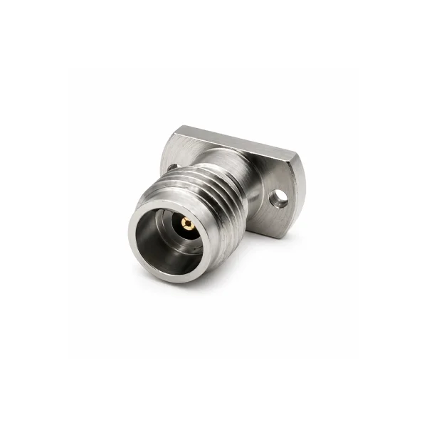
Solderless Straight Microstrip Connector
For repeatable 50 Ω microstrip PCB launches where solderless installation and replacement matter.
- DC–50 GHz 2.4mm female microstrip launch.
- Solderless mounting for faster installation cycles.
- Stable straight transition for precision microwave boards.
- Pad geometry and board layout reviewed before selection.

End Launch PCB Connector
For controlled board-edge transitions where connector-to-board registration affects RF continuity.
- DC–50 GHz 2.4mm female end launch structure.
- Compact end-launch format for dense PCB layouts.
- Suitable for test boards and evaluation fixtures.
- PCB stack-up, launch and grounding reviewed by drawing.
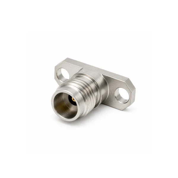
Vertical Mount Adapter Connector
For compact vertical RF transitions where the interface must align to a mounted geometry.
- DC–50 GHz 2.4mm vertical mount interface.
- Compact vertical transition for mounted RF geometry.
- Useful for fixtures, panels and compact RF paths.
- Mounted geometry and available height confirmed by drawing.
Want to browse all currently published 2.4mm connector products?
View all 2.4mm connector products →Features & applications
Built for 50 GHz microwave interconnects, panel transitions, feedthrough structures and board-level launch environments.
Key features
- DC to 50 GHz precision 50 Ω interface.
- Flange-mount, feedthrough, threaded input, vertical mount and end launch structures.
- Solderless microstrip and board-edge launch options for PCB validation.
- Drawing-based matching for panel, enclosure, fixture and PCB geometry.
- Additional 2.4mm connector variants available by request.
Typical applications
- Microwave test and measurement systems.
- Precision panel and fixture interfaces.
- Feedthrough and enclosure transitions.
- PCB launch and board-edge transitions.
- RF fixtures and evaluation platforms.
Structure reference & engineering support
Use the catalog structure families to shortlist the installation path first, then confirm model fit by drawing dimensions and final mating condition.
| Connector family | Best used when | Check first | Typical input | Next step |
|---|---|---|---|---|
| Removable Flange-Mount Connectors | A replaceable panel or fixture RF interface is required | Gender, flange pattern, mounting geometry | Panel drawing, mating side, socket bore / pin dimension | Request flange-mount match → |
| Feedthrough Connectors | A controlled RF path must pass through a panel, enclosure or bulkhead | Air / dielectric / metal structure, critical diameters, length | Wall thickness, enclosure boundary, feedthrough geometry | Request feedthrough match → |
| Threaded Input Connectors | A compact rear-thread or rear-retained panel input is required | Bore or pin dimensions, rear diameter, thread specification | Rear thread, panel thickness, retention method | Request threaded input match → |
| Vertical Mount Adapter Connectors | A compact vertical RF transition or mounted interface is required | Mounting pattern, contact geometry, mechanical fit | Mounted geometry, interface direction, available height | Request vertical adapter match → |
| End Launch Connectors | Board-edge RF launch transition is required | Launch geometry, board interface dimensions, contact profile | PCB stack-up, grounding pattern, launch geometry | Request end launch match → |
Common selection questions
What is a 2.4mm RF connector?
A 2.4mm RF connector is a precision 50 Ω coaxial interface designed for high-frequency interconnect applications up to 50 GHz.
When should I choose 2.4mm instead of 1.85mm or 2.92mm?
Choose 2.4mm for systems up to 50 GHz where a robust high-frequency interface is required. Choose 1.85mm for applications up to 67 GHz and 2.92mm for systems around 40 GHz.
How do I choose the right 2.4mm connector structure?
Choose by installation path: flange-mount for replaceable panel or fixture interfaces, feedthrough for wall or enclosure transitions, threaded input for rear-retained panel inputs, vertical mount for compact mounted geometry, and end launch for board-edge PCB transitions.
What information is required for a 2.4mm connector quote?
Please provide target frequency, connector family, interface gender, flange or thread details, PCB stack-up, panel or fixture drawing, available installation space and quantity.
Engineering review for 2.4mm connector integration
For microwave test systems, panel interfaces, feedthrough structures, solderless PCB launch or fixture interfaces, send your frequency target, mating condition and drawing for structure review, model matching and quotation support.