
1.00mm Precision RF Connectors
DC to 110 GHz, 50 Ω connector structures for PCB launch, solderless validation, panel ports and mmWave fixture integration.
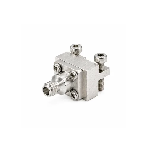
Choose by installation path
Start from the mechanical environment, then confirm dimensions, grounding pattern, and mating condition with the latest drawing.
End Launch PCB Connectors
For controlled board-edge transitions in W-band PCB test structures.
- DC–110 GHz precision PCB edge launch.
- Controlled coax-to-board transition.
- Suitable for W-band PCB validation.
- PCB thickness and launch geometry reviewed by drawing.

Solderless Vertical Launch
For no-solder validation on reusable mmWave boards and fixtures.
- Solderless installation for reusable test boards.
- Vertical launch structure for compact fixture layouts.
- Helps reduce rework during mmWave board validation.
- PCB stack-up and screw layout matched by drawing.

Straight PCB / Board Mount
For compact board-level RF ports where layout and installation space define fit.
- Compact board-mounted 1.00mm RF interface.
- Suitable for module, fixture and board-level RF ports.
- Multiple PCB layout and grounding variants available.
- Pad geometry and mounting holes confirmed by drawing.

Panel, Feedthrough & Flange
For panel walls, pin-accepting fixtures and removable flange structures.
- Panel, fixture-wall and feedthrough interface options.
- Flange-mount structures for removable RF interfaces.
- Glass bead / pin-accepting variants available.
- Mating side, bore and panel geometry reviewed by drawing.
Want to browse the currently published 1.00mm connector products?
View all 1.00mm connector products →Features & applications
Built for DC to 110 GHz board transitions, fixture interfaces and millimeter-wave validation environments.
Key features
- DC to 110 GHz precision 50 Ω interface.
- PCB edge launch, solderless vertical launch and board-mount structures.
- Panel, feedthrough and flange-style fixture options.
- Drawing-based matching for PCB stack-up, grounding and panel geometry.
- Additional 1.0mm connector variants available by drawing review.
Typical applications
- W-band and millimeter-wave test systems.
- Semiconductor validation boards.
- VNA and instrumentation front-panel ports.
- Precision RF fixtures and test jigs.
- mmWave module evaluation and R&D measurement platforms.
Structure reference & drawing support
Shortlist the connector structure first. Final model matching should be confirmed by PCB, panel or fixture drawing.
| Structure | Best used when | Drawing input | Frequency | Next step |
|---|---|---|---|---|
| End Launch PCB | RF path exits from the PCB edge | PCB thickness, launch geometry | DC–110 GHz | Request PCB launch match → |
| Solderless Vertical Launch | Reusable no-solder board validation is required | PCB stack-up, screw layout | DC–110 GHz | Send PCB stack-up → |
| Straight PCB / Board Mount | Compact board-level RF port is required | Pad geometry, mounting holes | DC–110 GHz | Check PCB layout → |
| Panel / Feedthrough / Flange | Interface is fixed to a panel or fixture wall | Panel drawing, mating side, bore | DC–110 GHz | Send fixture drawing → |
Common selection questions
What is a 1.00mm RF connector?
A 1.00mm RF connector is a precision 50 Ω coaxial interface for ultra-high-frequency signal transmission up to 110 GHz.
What frequency range can 1.00mm connectors support?
Vinstronics 1.00mm precision RF connector solutions are intended for DC to 110 GHz applications, depending on structure and installation condition.
How do I choose between end launch, solderless and panel-mount 1.0mm connector options?
Choose by installation path: PCB edge, reusable board validation, board-level RF port or panel / fixture-wall interface.
What information is required for a quote?
Please provide target frequency, connector structure, PCB or panel drawing, grounding pattern, available installation space and quantity.
Engineering review for 1.00mm connector integration
For PCB launch, solderless validation, panel or fixture interfaces, send your layout or mechanical drawing for structure review, model matching and quotation support.