
Engineer’s Selection Problem:
A 2.92mm connector can be rated to 40 GHz and still be the wrong choice if the PCB launch, panel thickness, feedthrough geometry, mating interface or installation structure does not fit the application.
Selecting a 2.92mm / K connector should not start with the model number alone. The right connector depends on the actual installation path: board-edge launch, solderless PCB validation, feedthrough transition, flange-mounted panel interface, cable assembly interface or adapter connection.
For product selection, review the Vinstronics 2.92mm RF connectors family, including PCB launch, solderless PCB, feedthrough, flange mount and related 2.92mm interface structures.
A 2.92mm connector, or K connector, is a compact precision threaded RF interface commonly used up to 40 GHz. Start with the required structure, then confirm frequency, gender, PCB or panel dimensions, mating condition and manufacturer rating.

What Is a 2.92mm / K Connector?
A 2.92mm connector is a precision coaxial connector used in RF and microwave systems where controlled signal transmission and repeatable mating are important. In common RF usage, the 2.92mm interface is also called the K connector.
Standard 2.92mm connectors are commonly 50 Ω and are widely used in DC–40 GHz microwave applications. They appear in test instruments, RF modules, evaluation boards, fixture interfaces, panel-mounted ports, feedthrough transitions and high-frequency cable or adapter paths.
Practical definition
A 2.92mm / K connector is not just a frequency label. It is a precision mechanical and electrical interface. The final result depends on the connector structure, mating interface, PCB launch, cable path or panel installation.
Key Technical Characteristics
The exact rating depends on the connector model, cable or PCB launch design and mating condition. The table below summarizes the typical engineering position of the 2.92mm / K interface.
| Parameter | Typical Position | Selection Note |
| Interface | 2.92mm / K connector | Precision threaded microwave coaxial interface. |
| Impedance | 50 Ω for standard versions | Special PCB launch structures may require separate impedance review. |
| Frequency range | Commonly used for DC–40 GHz applications | Final performance depends on structure, mating condition and manufacturer rating. |
| Typical structures | PCB launch, solderless PCB, feedthrough, flange mount, cable and adapter interfaces | Choose the structure by installation path before selecting a model number. |
| Common inputs for matching | Drawing, PCB layout, panel sketch, mating connector and target frequency | Model codes are helpful, but not required for first review. |
Common 2.92mm Connector Structures
In real applications, engineers usually choose a 2.92mm connector by mechanical structure first, then confirm electrical performance, footprint, mating condition and installation details.
End Launch PCB Connectors
End launch 2.92mm connectors are used for board-edge microwave transitions from PCB transmission lines into a coaxial K interface. PCB stack-up, grounding pattern and launch geometry should be reviewed before selection. For product-level examples, review a Vinstronics 2.92mm end launch PCB connector example. For broader background, see the Vinstronics end launch connector guide.
Vertical Solderless PCB Connectors
Solderless or compression-style 2.92mm PCB connectors are useful for repeatable test boards, evaluation boards and prototype validation where removable installation is valuable. The PCB layout, screw pattern and compression condition must be reviewed. For product-level examples, review a Vinstronics 2.92mm vertical solderless PCB connector example.
Feedthrough Connectors
Feedthrough structures are selected when the RF signal must pass through a module wall, housing, panel or defined mechanical boundary while maintaining a controlled microwave transition.
Flange Mount and Panel Mount Connectors
Flange mount 2.92mm connectors provide a mechanically stable interface for front panels, fixtures, module ports and replaceable RF test connections. For product-level examples, review a Vinstronics 2.92mm flange mount PCB connector example.
Cable and Adapter Interfaces
2.92mm cable and adapter interfaces are used to connect test instruments, microwave cable assemblies and adjacent connector families in lab or system-level RF paths.
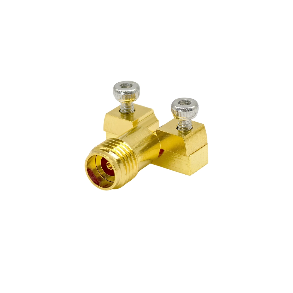
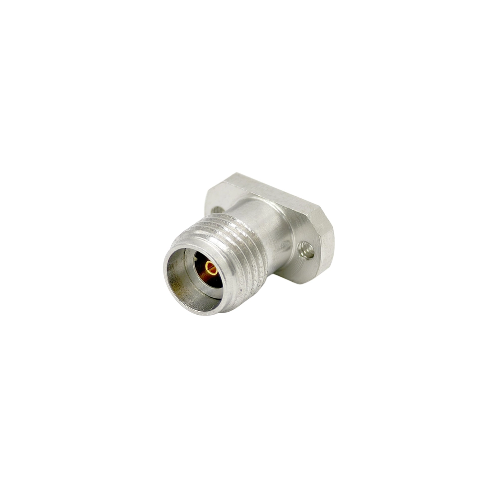

The examples above illustrate common 2.92mm connector structures. For the complete archive, see Vinstronics 2.92mm connector products.
2.92mm vs SMA, 3.5mm and 2.4mm Connectors
The 2.92mm / K interface is often selected when a compact precision connector is required for DC–40 GHz systems, especially where SMA is not sufficient and 2.4mm may be more than required.
| Interface | Typical Position | Selection Note |
| SMA | General RF and lower-frequency microwave systems | Common and versatile, but not ideal for repeated precision 40 GHz use. Review the Vinstronics SMA connector category where a lower-frequency interface is sufficient. |
| 3.5mm | Precision microwave interface below the 2.92mm frequency ceiling | Often mechanically compatible with 2.92mm, but mating condition and connector wear should be checked. |
| 2.92mm / K | DC–40 GHz precision microwave interconnects | Good balance of frequency, size and compatibility for 40 GHz test, PCB launch and module interfaces. |
| 2.4mm | Higher-frequency precision systems | Used when additional frequency margin above 40 GHz is required. Review Vinstronics 2.4mm RF connectors for higher-frequency interface needs. |
For a focused comparison, see the Vinstronics article: 2.92mm Connectors vs SMA.
How to Choose a 2.92mm Connector
Start with the installation structure, then confirm the electrical and mechanical details that determine whether the connector will fit the board, panel or test environment.
Structure-first selection logic
- Choose end launch structures for board-edge microwave transitions.
- Choose solderless PCB structures for repeatable board validation without soldering.
- Choose feedthrough structures for enclosure-wall, module-wall or panel transitions.
- Choose flange mount structures for mechanically stable panel or fixture interfaces.
- Send a drawing, PCB layout or panel sketch when the structure is not clear.
Common selection mistake
Do not select a 2.92mm connector by frequency alone. A connector rated to 40 GHz can still be unsuitable if the launch geometry, flange pattern, panel thickness, mating interface or grounding condition does not fit the application.
What to Send for a 2.92mm Connector Quotation
A model number is helpful, but the first connector review can usually begin from a drawing, layout or mechanical sketch. The more complete the input, the easier it is to match the correct connector structure.
Send these details
- Target frequency range
- Connector gender and mating interface
- Mounting structure
- PCB thickness or panel thickness
- Transmission line type
- Drawing, layout file or panel sketch
- Mating connector condition
- Quantity and application environment
Typical Applications
2.92mm connectors are used where 40 GHz microwave performance, compact size and reliable threaded mating are important. Typical application areas include:
- Microwave test and measurement: VNA test setups, fixtures, calibration paths and instrument front-panel interfaces.
- RF modules and compact assemblies: Module interfaces, compact RF assemblies and high-frequency interconnect paths.
- PCB evaluation and validation: Test boards, evaluation boards and prototype fixtures where launch geometry must be reviewed.
- Radar and communication systems: Microwave links and controlled RF transitions in communication equipment.
- Satellite and aerospace RF links: Selected RF paths where mating quality and environmental requirements are reviewed at the design stage.
- Production and lab testing: Lab measurement, engineering validation and production test environments.
Download the 2.92mm RF Connectors Selection Guide
The Vinstronics 2.92mm RF Connectors Selection Guide summarizes DC–40 GHz K connector structures for PCB launch, solderless mounting, feedthrough, flange and panel applications.
What the guide helps review
- Structure selection reference for 2.92mm connector families
- PCB, panel, feedthrough and solderless structure notes
- RFQ checklist for drawing-based connector matching
Engineering resource
For structure selection, PCB launch review and RFQ preparation, download the Vinstronics 2.92mm RF Connectors Selection Guide.
Conclusion
A 2.92mm / K connector should be selected as part of the full RF interconnect structure, not as an isolated model number. The right choice depends on frequency range, connector gender, PCB or panel geometry, mating condition, feedthrough or flange structure, and the complete RF path.
For available product structures, review the Vinstronics 2.92mm RF connector family.
Selection rule:
Start with the installation structure, then confirm the 2.92mm connector model.
FAQ
What is a 2.92mm connector?
A 2.92mm connector, also called a K connector, is a precision 50 Ω microwave coaxial interface commonly used for DC–40 GHz signal transmission.
Is a 2.92mm connector the same as a K connector?
In common RF and microwave usage, 2.92mm connector and K connector usually refer to the same precision connector interface.
What frequency range does a 2.92mm connector support?
2.92mm connectors are commonly used for DC–40 GHz applications. Final performance depends on structure, launch design and mating condition.
Can 2.92mm connectors mate with SMA or 3.5mm connectors?
They are often mechanically compatible, but connector wear, mating condition and target frequency should be checked before precision use.
When should I choose 2.92mm instead of 2.4mm?
Choose 2.92mm for DC–40 GHz applications. Choose 2.4mm when additional frequency margin above 40 GHz is required.
What is a 2.92mm end launch connector used for?
It is used for board-edge microwave transitions from a PCB transmission line to a coaxial K connector interface.
What information is needed for quotation?
Useful inputs include frequency, gender, mounting structure, PCB or panel thickness, transmission line type, drawing, layout file and quantity.
Need help matching a 2.92mm connector?
If the connector structure is unclear, send the drawing, PCB layout or panel sketch for review before selecting a model.

