
Material, plating, RF and environmental requirements for MRI, quantum, cryogenic and field-sensitive systems.
“Non-magnetic” is not a complete connector specification. A reliable selection starts with the entire material and plating system, then defines magnetic acceptance, RF performance and operating environment as separate requirements.
This guide shows the technical inputs needed to evaluate a non-magnetic connector without assuming that one construction is suitable for every MRI, quantum, cryogenic or laboratory system.
Define “Non-Magnetic” as an Acceptance Requirement
The term may mean avoiding conventional ferromagnetic materials, meeting a low susceptibility or permeability limit, controlling residual field, or passing a customer-defined magnetic test. These are not equivalent specifications.
Whenever possible, write the requirement as a measurable acceptance condition. A useful specification may include:
- Permitted and prohibited material grades
- Housing, center-contact and spring-contact materials
- Underplating and final plating restrictions
- Susceptibility, permeability or residual-field limits
- Measurement method, orientation and distance
- Preconditioning or external-field exposure
- Required material declarations
- Required test reports or lot-level verification
When no numerical limit has been defined, state the application context clearly. “Near an MRI receive coil,” “inside a dilution refrigerator,” or “for a field-sensitive laboratory instrument” is more useful than the word “non-magnetic” alone.
Review the Complete Material and Plating Construction
The visible finish does not define the magnetic behaviour of the complete connector. Gold may be applied over different underplating systems, and a compliant housing may still contain a spring, screw or retainer that does not meet the project requirement.
Copper-based alloys, including beryllium copper, are commonly used where conductivity and spring performance are required. The exact alloy, heat treatment and plating construction still need confirmation. Likewise, “nickel-free” may remove one contributor but is not a complete qualification.
Keep Magnetic, RF and Environmental Requirements Separate
Define acceptance
- Materials and plating restrictions
- Susceptibility, permeability or residual field
- Measurement method and acceptance limit
- Documentation or lot-level testing
Define performance
- Interface, gender and 50 Ω impedance
- Maximum operating frequency
- VSWR / return loss and insertion loss
- Power, shielding and mating requirements
Define integration
- Temperature and thermal cycles
- Vacuum or hermeticity, when required
- Vibration, shock and mating life
- Cable, PCB, panel or module mounting
Select the Interface by Mechanical Integration
Choose the interface according to mating, retention, available space and mounting structure before selecting a final model. The ranges below apply to currently published Vinstronics products and remain model-dependent.
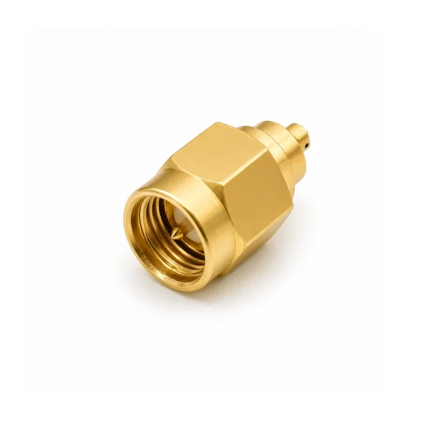
SMA
Threaded interface for accessible cable connections, equipment ports and locations where secure mating is preferred.
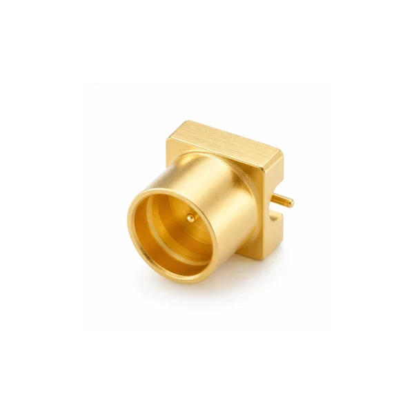
SMP
Compact push-on interface for PCB, module and blind-mate layouts. Detent, float, alignment and retention must also be defined.
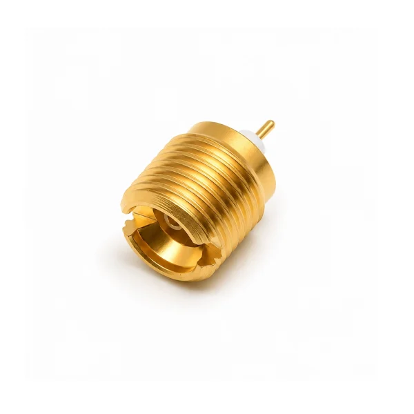
SSMP
Miniature interface for compact, higher-density layouts where footprint, mating geometry and assembly clearance are tightly constrained.
Non-Magnetic and Cryogenic Are Related—but Different
These requirements often appear together in superconducting and quantum systems, but they address different engineering risks.
Non-Magnetic Review
- Complete material and plating construction
- Restricted or prohibited materials
- Magnetic acceptance criterion
- Measurement method and documentation
Cryogenic Review
- Thermal contraction and contact-force retention
- Dielectric behaviour and heat flow
- Repeated cool-down cycles
- Position within the cryogenic stage map
A connector suitable for a low-magnetic room-temperature instrument may not be qualified for repeated cryogenic operation. Conversely, a cryogenic connector may not meet a particular magnetic-cleanliness requirement. State both conditions independently.
Common Specification Mistakes
Non-Magnetic RF Connector Specification Checklist
Use this checklist when requesting a standard-product review or a drawing-based custom evaluation.
Project Input Sheet
Provide the available project information so the interface, materials, RF performance and environmental requirements can be reviewed together.
Application & Magnetic Acceptance
- System and connector location
- Acceptance criterion and test method
- Measurement orientation and distance
- Restricted materials or plating
RF Requirements
- Interface, gender and mating part
- Impedance and maximum frequency
- VSWR / return loss and insertion loss
- Power or shielding requirement
Mechanical Integration
- Cable, PCB, panel or module mounting
- Orientation, retention and envelope
- Mounting holes and PCB footprint
- 2D drawing, STEP file or sample
Environment & Programme
- Temperature, cryogenic stage and cycles
- Vacuum, hermeticity, vibration or shock
- Prototype and production quantities
- Delivery and validation documents
Current Options and Related Resources
Frequently Asked Questions
What makes an RF connector non-magnetic?
A connector must use a complete material and plating construction selected against a defined low-magnetic requirement. Housing, contacts, springs, fasteners, underplating and assembly materials may all require review.
Is a nickel-free connector automatically non-magnetic?
No. Removing conventional nickel underplating may reduce one contributor, but the full construction still needs to be reviewed against the project acceptance criterion.
Are non-magnetic connectors automatically suitable for cryogenic systems?
No. Cryogenic suitability requires a separate review of temperature, thermal contraction, contact stability, dielectric behaviour and cycle conditions.
How do I choose between SMA, SMP and SSMP?
Use SMA where a threaded accessible connection is preferred; SMP for compact push-on PCB or module connections; and SSMP where a smaller, denser interface is required. Frequency, mating geometry, mounting and retention determine the final model.
What should I send for engineering review?
Provide the application, magnetic acceptance criteria, interface, maximum frequency, mounting structure, environment, quantity and any drawing, PCB footprint, STEP file or mating-part information.
Request a Non-Magnetic Connector Review
Send the interface, frequency, mounting structure, material restrictions, magnetic acceptance criteria and operating environment.
Interface · frequency · mounting · magnetic criteria · environment

