
RF Power Dividers
Split one RF path into controlled output branches
RF power dividers and splitters for distributing one input signal across multiple output paths in DAS, antenna systems, RF test setups and indoor coverage networks—organized by way count, frequency band, input power and connector interface.
Fast inputs: way count • frequency band • connector • impedance • input power • balance target • quantity.

Start with output count
Power divider selection becomes clearer when the branch count is confirmed before detailed model numbers.
Note: split loss is determined by the number of ways, while practical insertion loss, isolation and balance are model-dependent.
Find the right power split path fast
The published N-female models cover common 2-way, 3-way and 4-way indoor signal distribution needs. For higher-way, different connector, or wider-band requirements, send the system input for engineering review.
2-Way Power Divider

- •One input split into two output branches
- •698–2700 MHz, 50 W N-female published model
- •Good starting point for simple RF distribution
3-Way Power Divider
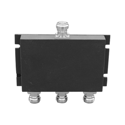
- •One input distributed across three branches
- •Published model with 698–2700 MHz band and 50 W input power
- •Useful when three balanced output paths are required
4-Way Power Divider

- •One input distributed across four RF branches
- •Published 698–2700 MHz, 50 W N-female option
- •Practical for antenna and indoor coverage layouts
6-Way / 8-Way / 12-Way Review
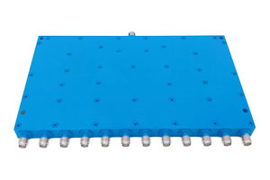
- •For more output branches or special layouts
- •Reviewed by frequency, power and balance targets
- •Best when no published model fits directly
What should be confirmed before choosing a power divider?
Expand to check the core inputs needed for accurate model matching.
View checklist ↓
Frequently Asked Questions
How do I choose between 2-way, 3-way and 4-way RF power dividers?
Start from the number of output branches required by the system. A 2-way divider suits two equal paths, 3-way supports three branches, and 4-way is used when one RF feed must be distributed to four antennas, devices or test paths.
What information is needed to select an RF power divider?
Provide the operating frequency range, number of output ways, impedance, connector interface, input power, insertion loss target, isolation requirement, VSWR target and indoor or outdoor application environment.
What is the difference between split loss and insertion loss?
Split loss is the theoretical power division loss caused by splitting one signal into multiple paths. Insertion loss is the additional practical loss introduced by the divider structure, connectors and internal transmission path.
Why do amplitude balance and phase balance matter?
Amplitude and phase balance help keep the output paths consistent. This is important in antenna distribution, DAS, measurement setups and systems where multiple branches must receive predictable RF power.
Can Vinstronics support higher-way or custom RF power divider configurations?
Yes. Published products can be used as starting points, and higher-way or application-specific configurations can be reviewed by frequency range, connector interface, power level and mechanical requirements.
Ready to shortlist the right RF power divider?
Share output count, frequency band, input power, connector interface, impedance and balance requirements. We’ll help match the published model or review a higher-way configuration.