
RF Coaxial Switches
Topology-first selection for RF test paths
A clean switch selection page for routing RF and microwave signals in automated test systems, switch matrices, lab setups, and production fixtures—covering SPDT, DPDT, SP3-6T, and high-port-count multi-throw configurations.
Fast inputs: topology • port count • interface • frequency • terminated/non-terminated • control voltage • qty.

Start with the routing path
RF switch selection is clearer when topology comes before model numbers.
Note: insertion loss, isolation, power handling and control details are model-dependent. Submit the routing requirement for verification.
Find your RF switch family fast
These families match the most common RF routing decisions: simple A/B path switching, paired line switching, multi-DUT routing, and higher-port-count switch matrix builds.
SPDT Coaxial Switches
- •One input to two RF paths
- •A/B routing and test path selection
- •SMA, N, 2.92, 2.4, 1.85 mm paths
DPDT Coaxial Switches
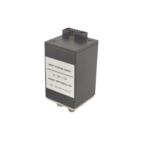
- •Two RF paths switched together
- •Fixture and system-level routing
- •SMA, 2.92 mm and 2.4 mm examples
SP3-6T RF Switches
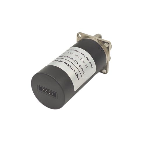
- •One path to several outputs
- •Multi-DUT or instrument routing
- •Mini and short-body options by series
SP7-10T RF Switches

- •Higher-port-count path selection
- •SP7-8T and SP10T options
- •Automated test and switch matrix use
Need a specific interface, control method, or terminated option?
Expand to check the main inputs needed for switch matching.
View checklist ↓
Frequently Asked Questions
How should I choose between SPDT, DPDT and multi-throw RF switches?
Start from the routing topology. Use SPDT for one input switched between two paths, DPDT for paired path switching, and SP3T to SP10T configurations when one signal path must be routed across multiple instruments, DUTs or test paths.
Should I select terminated or non-terminated RF coaxial switches?
Terminated switches can help control unused-port behavior in selected test setups. Non-terminated switches may be suitable for simpler routing paths. The choice should be reviewed against the signal path and measurement architecture.
Which connector interface is suitable for an RF coaxial switch?
Choose the interface by frequency range and mating system. SMA and N-type are common in many RF systems, while 2.92 mm, 2.4 mm and 1.85 mm interfaces are used for higher-frequency microwave paths when required.
What information is needed for RF switch matching?
Provide the switching topology, port count, connector interface, frequency range, terminated or non-terminated requirement, latching or failsafe mode, control voltage, pin style, RF power target and quantity.
Ready to shortlist the right RF switch?
Share topology, port count, frequency, interface, terminated/non-terminated requirement, and control method. We’ll help match the switch family and quotation path.