
Phase-Stable Flexible Cable
Engineered for precision microwave routing and phase-critical measurement paths.
Designed for RF interconnects requiring absolute or relative phase tracking across temperature fluctuations and mechanical movement. This family delivers stable electrical behavior for precision test systems and phase-sensitive environments.
What is Phase-Stable Cable?
A microwave interconnect utilizing an advanced low-density dielectric structure. It minimizes phase shift when the cable is flexed, routed, or exposed to temperature variations.
The Engineering Value
Ensures calibration integrity in metrology setups and maintains signal coherence in complex arrays. By mitigating unpredictable electrical variance, it allows engineers to isolate true device performance.
Why Choose This Family?
Phase Repeatability
Delivers highly consistent phase behavior across temperature sweeps, safeguarding measurement accuracy.
Flexure Stability
Maintains amplitude and phase coherence even when the cable is actively moved or routed during testing.
Precision Test Suitability
Engineered to support advanced microwave applications, ensuring reliable signal transmission for critical metrology setups.
Model Performance Overview
A faster way to compare the phase-stable family by the two parameters customers usually care about most: attenuation and temperature phase stability.
Reference Attenuation Comparison
Representative models plotted from published datasheet attenuation values.
Temperature Phase Stability Comparison
Representative models compared by published phase-vs-temperature stability across the stated temperature range.
How to read this section: thinner platforms generally preserve higher usable frequency but show higher attenuation. Larger platforms usually reduce attenuation, but require more routing space and larger bend radius. For phase-stable selection, customers usually balance frequency target, loss budget, phase-vs-temperature requirement, and routing envelope together rather than optimizing only one parameter.
Recommended Decision Table
Key parameters selected to support faster model screening for real customer decisions.
| Model | OD (mm) | Fmax (GHz) | Phase vs. Temp (ppm) | Attenuation @ 10 GHz | Static Bend Radius (mm) | Best Fit |
|---|---|---|---|---|---|---|
| W15 | 1.5 | 128 | <1000 ppm | 368.0 dB/100m | 8 | Highest-frequency compact routing |
| W22 | 2.2 | 83 | <750 ppm | 209.8 dB/100m | 8.8 | Compact mmWave / metrology |
| W36 | 3.6 | 46 | <750 ppm | 122.3 dB/100m | 18 | Balanced loss vs routing size |
| W40 | 4.0 | 41 | <750 ppm | 107.2 dB/100m | 20 | Mainstream precision RF choice |
| W50 | 5.2 | 29 | <750 ppm | 76.3 dB/100m | 26 | Lower loss with broader thermal margin |
| W76D | 7.65 | 18 | <750 ppm | 55.0 dB/100m | 38 | Higher power / larger routed systems |
| W80 | 7.9 | 18 | <750 ppm | 48.8 dB/100m | 39 | Lower loss high-power routing |
| W100 | 10.0 | 13.5 | <750 ppm | 36.1 dB/100m | 41 | Heavy-duty low-loss installation |
| W120 | 12.0 | 11 | <750 ppm | 31.0 dB/100m | 60 | Lowest loss / largest routing envelope |
Note: Fmax represents the theoretical cut-off frequency of the raw cable. System operating frequency depends on selected connector interfaces.
Representative Assemblies
Assembly-level examples for customers who need complete test leads rather than raw cable only.
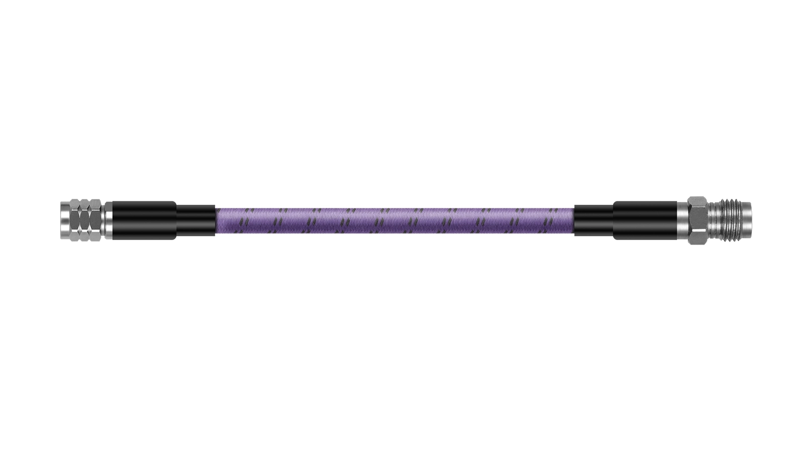
Precision Testing Cable Assembly
Configured for production-floor test and online measurement environments where amplitude stability, manageable bend radius, and repeatable handling all matter.
- VSWR ≤1.25 @ 26.5 GHz
- Amplitude Stability ±0.05 dB @ 26.5 GHz
- Mechanical Phase Stability ±5° @ 26.5 GHz
- Interface Options SMA, N, 3.5mm, 2.92mm, 2.4mm
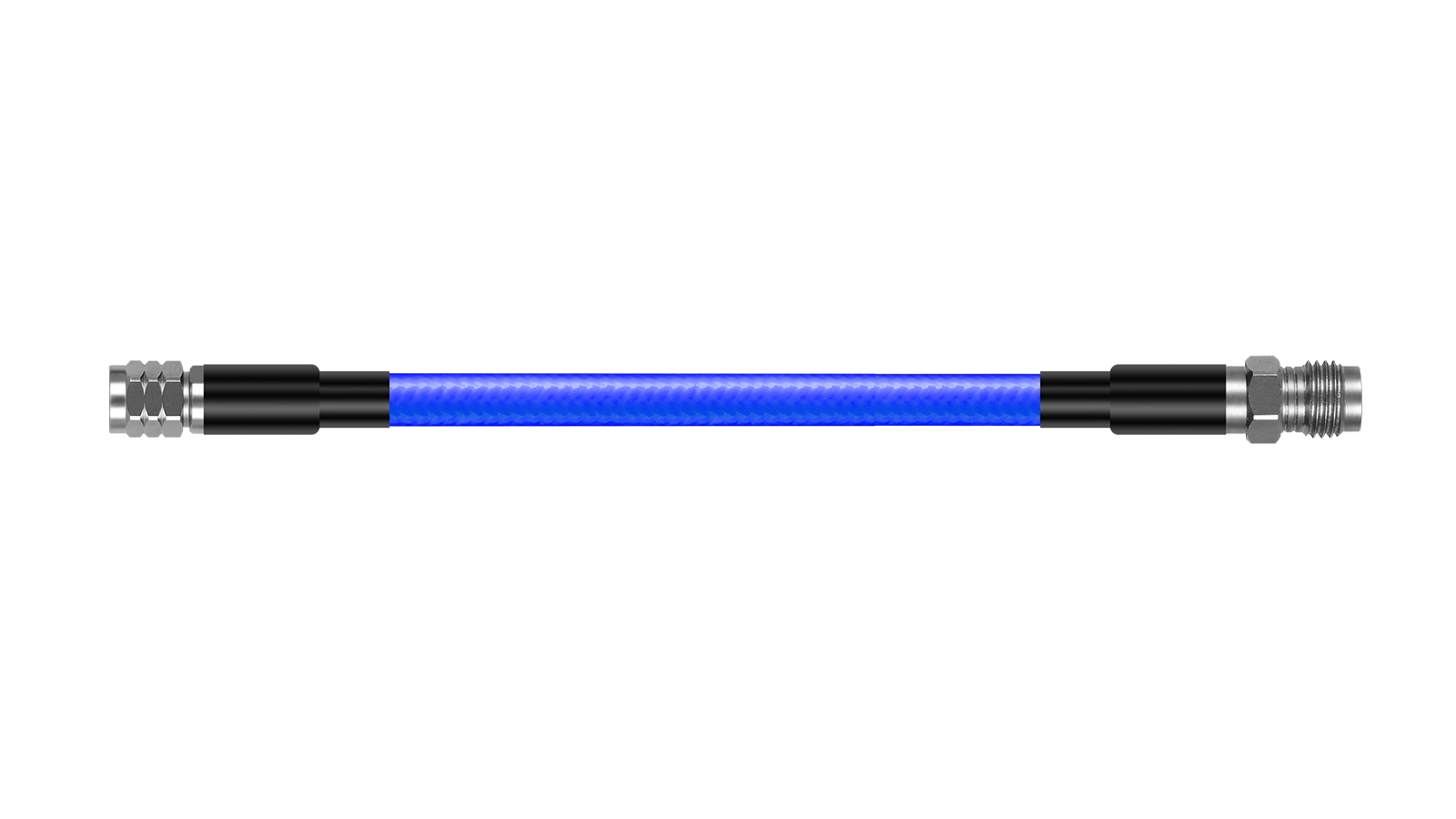
110 GHz Cable Assembly
Built for very high-frequency interconnect paths where connector precision, controlled phase behavior, and compact routing are all critical at the assembly level.
- Working Frequency 110 GHz
- Amplitude Stability ±0.2 dB @ 110 GHz
- Mechanical Phase Stability ±15° @ 110 GHz
- Cable Package HC150 / HC150KJ
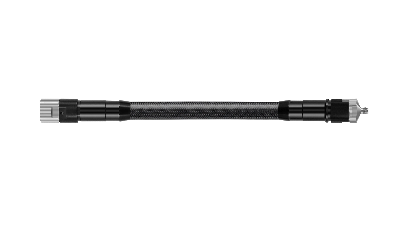
VNA Test Cable Assembly
Optimized for vector network analyzer workflows that demand long bend life, controlled mechanical phase stability, and repeatable high-frequency measurement behavior.
- Amplitude Stability ±0.03 dB @ 40 GHz / ±0.05 dB @ 67 GHz
- Mechanical Phase Stability ±5° @ 67 GHz
- Bend Life Up to 2,000,000 cycles
- Interface Options N, 3.5mm, 2.92mm, 2.4mm, 1.85mm
Typical Applications
VNA & Metrology Routing
Ensuring calibration integrity and measurement repeatability during test lead handling.
Phased-Array Systems
Delivering phase coherence across multiple antenna elements and beamforming networks.
Semiconductor ATE Validation
Maintaining stable electrical performance during automated testing processes.
Production Test & Online Measurement
Supporting cable assemblies used in production-floor measurement and inline RF verification.
Aerospace & Defense
Reliable phase tracking over wide temperature variations in avionics, radar, and electronic countermeasure systems.
High-Frequency Device Characterization
Supporting microwave and mmWave component evaluation where amplitude and phase variation must remain controlled.
Key Technical Considerations
Phase Shift vs. Temperature
Dielectric materials naturally expand or contract with temperature. Phase-stable constructions utilize specialized dielectrics to keep phase variance within strictly controlled limits across thermal extremes.
Insertion Loss Stability
Maintaining amplitude stability during physical movement is critical. High-quality shielding and precise jacket extrusion prevent insertion loss spikes when the cable is flexed.
Routing Bend Control
Exceeding the minimum bend radius permanently deforms the dielectric, degrading phase stability. Spatial constraints must be evaluated when selecting the cable's outer diameter.
Connector Interface Precision
Performance heavily depends on the connector transition. Terminations must be expertly matched using precision interfaces to prevent reflection and preserve phase integrity.
Custom Assemblies & Engineering Support
Custom Routing Lengths
Precision-cut assemblies ensuring exact physical and electrical lengths for your setup.
Phase-Matched Builds
Support for relative or absolute phase-controlled multi-port routing requirements.
Assembly-Level Verification
Available validation for VSWR, amplitude stability, phase behavior, and other RF criteria depending on configuration.
Engineering Recommendation
Direct assistance in selecting cable platform, outer diameter, bend radius, interfaces, and assembly structure.
Related Flexible Cable Families
If phase stability is not your only priority, these adjacent families may also be relevant.

High-Power RF Cable
For higher CW power, amplifier feeds, and broader thermal margin.
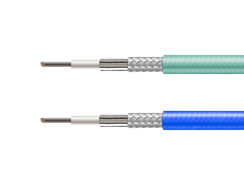
Low-Loss Flexible Cable
For attenuation-sensitive broadband routing where loss is the primary filter.

Ultra-Flexible RF Cable
For tighter bend routing, denser layouts, and more demanding mechanical flexibility.
Phase-Stable Cable FAQ
What is a phase-stable flexible cable?
It uses a specialized dielectric to minimize phase shift when exposed to temperature variations or mechanical flexure.
When should I choose phase-stable over standard flexible cable?
Choose this family when absolute or relative phase tracking is required to maintain system calibration.
Is phase-stable cable suitable for VNA test setups?
Yes. They are the standard for Vector Network Analyzer (VNA) metrology, ensuring measurement repeatability.
Can Vinstronics provide connector-installed assemblies?
Yes. We supply factory-terminated assemblies with precision interfaces, verified for structural and electrical integrity.
Does cable routing affect phase stability?
Yes. Bending alters physical geometry slightly, making adherence to recommended minimum bend radiuses critical.
What information should I provide for a recommendation?
Provide your target frequency range, length, connector type, routing constraints, and any phase-tracking requirements.
Flexible RF Cable Selection Guide
Download the technical overview for family comparisons and structural data (PDF).
Discuss Your Phase-Stable Cable Requirement
Our engineering team is ready to recommend the optimal phase-stable configuration for your system. We assist with phase tracking goals, connector selection, and custom assembly routing.
Typical inputs: frequency range, cable length, bend constraint, connector type, phase targets
Request an Engineering Recommendation