
Engineer’s Pain Point:
If your AI validation board uses 500µm, 800µm, 1000µm, or custom differential pads, a standard wafer probe may not be the right fit. Adding a fixture can solve the contact problem — but it may also add loss, reflection, skew, and uncertainty to the measurement path.
A 67GHz large-pitch GSSG differential RF probe is often needed when engineers need to test high-speed differential structures directly on AI chip validation boards, SerDes test boards, package coupons, or PCB-level test vehicles. In these setups, the challenge is not only reaching 67GHz. The real challenge is matching the pad layout, keeping the contact repeatable, and avoiding fixture transitions that can hide the true DUT performance.
The Vinstronics VST-67G-GSSG is a DC–67GHz large-pitch GSSG differential RF probe for AI accelerator validation boards, high-speed SerDes test boards, PAM4 channels, package coupons, and PCB-level differential measurements. It supports 100µm to 1250µm pitch options, with custom pitch configurations available for non-standard DUT layouts.

Quick Engineering Summary
| Frequency Range | DC–67GHz |
| Tip Configuration | GSSG differential contact |
| Pitch Range | 100µm to 1250µm, custom pitch available |
| RF Interface | 1.85mm Female |
| Connector Angle | 45-degree |
| Best Fit | AI chip validation boards, SerDes test boards, PAM4 channels, package coupons, and high-speed PCB differential structures |
What Is a Large-Pitch GSSG Probe?
A large-pitch GSSG probe is a differential RF probe with a ground-signal-signal-ground tip layout and wider pad spacing. It is used when the DUT has board-level or package-level differential pads that do not match standard wafer-probe pitch.
In high-speed validation work, this matters because the probe is not just a contact tool. It becomes part of the differential measurement path. If the pitch, contact geometry, or fixture transition is wrong, the measured SDD11 / SDD21 result may reflect the setup instead of the DUT.
Why Large-Pitch Differential Probing Matters on AI Chip Validation Boards
AI chip validation boards and high-speed SerDes test boards often use differential pads that are larger and more widely spaced than standard wafer-level RF pads. This is common on AI accelerator validation boards, GPU and switch ASIC evaluation boards, 112G and next-generation SerDes test boards, PAM4 channel validation boards, package-level test coupons, and high-speed PCB interconnect structures.
When the probe pitch does not match the DUT layout, engineers may need soldered coaxial cables, SMA launches, temporary fixtures, or transition boards. Each added transition can introduce insertion loss, reflection, skew, and repeatability uncertainty. A large-pitch GSSG RF probe helps engineers contact the differential pads directly and keep the measurement path easier to control.

Where the Problem Usually Appears
- AI accelerator validation boards with large differential test pads
- 112G and next-generation SerDes test boards and PAM4 channel validation setups
- Package coupons and advanced interconnect test structures
- High-speed PCB differential coupons where SMA launches may distort the result
- Dense test boards where bulky fixtures are difficult to place repeatedly
The Main Pain Points in High-Speed Differential Board Testing
1. The probe pitch does not match the board-level pad layout
The problem: Many validation boards use 500µm, 800µm, 1000µm, or custom differential pad spacing instead of standard wafer-probe pitch.
The risk: Board modifications or transition fixtures can change the measurement result and make the RF path harder to control.
How VST-67G-GSSG helps: It supports 100–1250µm pitch options and custom pitch configurations for large-pitch differential pads.
2. Fixture transitions can hide the real DUT performance
The problem: At high data rates, the probe, cable, connector, launch, and fixture all become part of the measurement path.
The risk: A poorly controlled transition can make it difficult to know whether a return-loss issue comes from the DUT or from the setup.
How VST-67G-GSSG helps: Direct GSSG probing helps engineers evaluate SDD11 and SDD21 with fewer uncertainties from extra contact interfaces.
3. Differential path symmetry matters
The problem: High-speed differential testing is sensitive to signal path mismatch, skew, and asymmetry in the probing path.
The risk: Even small imbalance can affect phase response, repeatability, and mixed-mode S-parameter interpretation.
How VST-67G-GSSG helps: The GSSG contact structure provides a controlled ground-signal-signal-ground interface for balanced differential pads.
4. Dense test boards leave limited room for bulky fixtures
The problem: AI accelerator boards and SerDes test vehicles often place differential pads close to packages, connectors, or neighboring channels.
The risk: Large external fixtures can be difficult to place, difficult to repeat, and slow during multi-point debugging.
How VST-67G-GSSG helps: The compact probe body, 1.85mm female interface, and 45-degree connector angle help keep the setup practical for probe station or positioner use.
Why 67GHz Bandwidth Matters for 112G SerDes and PAM4 Validation
For 112G SerDes and PAM4 systems, engineers need more than low-frequency continuity checks. They need to understand insertion loss, return loss, discontinuities, and differential channel behavior across a wide frequency range.
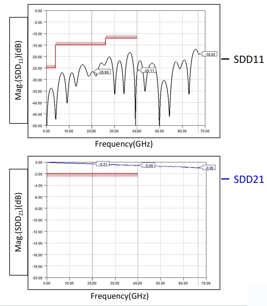
For differential validation, SDD21 shows how much of the differential signal is transmitted through the DUT path, while SDD11 reflects how much energy is reflected back from the differential input. These mixed-mode parameters are more relevant than single-ended S-parameters when engineers are debugging balanced SerDes channels, package transitions, and board-level differential interconnects.
A DC–67GHz differential probe gives engineers more headroom when validating high-speed interconnects, package transitions, and board-level differential channels. The value is not only “reaching 67GHz.” The real value is reducing uncertainty in a complex differential measurement setup.
Engineering Note
When comparing probe options for AI chip validation boards or high-speed SerDes test boards, do not evaluate frequency range alone. Check pitch match, GSSG pad access, cable routing, calibration method, and whether measured SDD11 / SDD21 data is available for engineering review.
Measured GSSG500 Data Available for Engineering Review
For high-speed differential probing, engineers often need more than a catalog specification. They need to understand how the probe behaves in a real measurement setup, especially when the measurement path includes a probe station, RF cables, adapters, calibration substrate, and a high-speed DUT.
Example Test Configuration
| Probe Type | GSSG500 |
| Pitch | 500µm |
| Connector Type | 1.85mm |
| Max Frequency | 67GHz |
| Measured Data | SDD11 / SDD21 reference data available |
| Recommended Overtravel | 50–70µm |
| Recommended Skate | 20–30µm |
Why Probe-Tip Calibration Matters
For board-level and package-level differential validation, the calibration plane should be moved as close as practical to the probe tip. This helps engineers separate DUT behavior from cable, adapter, fixture, and launch effects.
When calibration is not handled carefully, the measured return loss or insertion loss may include errors from the test setup. For high-speed SerDes, PAM4, and AI chip validation boards, this can make the engineer debug the fixture instead of the DUT.
Selection Checklist for 67GHz GSSG Probing
- Confirm the DUT pad pitch before selecting the probe.
- Check whether the DUT layout requires GSSG or GSGSG contact geometry.
- Confirm target frequency range and VNA connector setup.
- Review the complete RF path: probe, cable, adapter, fixture, and calibration substrate.
- Ask whether measured SDD11 / SDD21 data is available for the selected configuration.
For a deeper look at pitch mismatch, fixture transitions, and contact repeatability, read our technical article on
why large-pitch GSSG probing matters in high-speed PCB and AI chip validation.
Send your DUT pad layout or board photo. Vinstronics engineers can review whether a standard or custom GSSG pitch is required before you select the probe.
Typical Applications
- AI chip validation boards: Direct probing of large-pitch differential pads on AI accelerator, GPU, or switch ASIC validation platforms.
- High-speed SerDes test boards: Differential probing for 112G and next-generation SerDes lanes, PAM4 channels, and board-level channel debugging.
- Package and PCB coupons: Measurement of package transitions, differential PCB coupons, and non-standard high-speed test structures.
- mmWave differential circuits: Characterization of differential mmWave components, TRX structures, and high-speed mixed-signal test vehicles.
For adjacent RF probing configurations, engineers can also review Vinstronics RF Probe, GSSG Probe, and GSGSG Probe options depending on DUT layout and isolation requirements.
When Should Engineers Use a Large-Pitch GSSG Probe Instead of a Fixture?
A large-pitch GSSG probe is usually a better option when the DUT already provides accessible differential pads and the engineer wants to avoid adding a permanent or temporary transition structure. This is common during early validation, board bring-up, package coupon measurement, and multi-point debugging.
A fixture may still be useful when the DUT does not provide probe-accessible pads, when mechanical stability is more important than flexibility, or when the same test must be repeated at production scale. For R&D and validation work, however, direct GSSG probing often gives engineers a faster and cleaner way to evaluate the differential path.
Pitch Options and Configuration
Board-level and package-level test structures do not always follow a standard pad pitch. This is why pitch selection is one of the most important details when choosing a GSSG probe.
| What to Check | Recommended Direction | Why It Matters |
| DUT pad pitch | Match probe pitch or request custom pitch | Avoids unnecessary transition fixtures and contact mismatch. |
| DUT type | PCB, package coupon, wafer, or validation board | Affects access angle, pitch, contact force, and calibration method. |
| Frequency target | DC–67GHz | Determines probe, connector, cable, and VNA path requirements. |
| Tip configuration | GSSG differential contact | Suitable for balanced differential pads and mixed-mode S-parameter measurement. |
| RF interface | 1.85mm Female | Supports high-frequency connection to VNA and RF test setups. |
| Connector angle | 45-degree | Helps access dense boards with a practical cable path. |
Common configurations may include VST-67G-GSSG-150, VST-67G-GSSG-250, VST-67G-GSSG-500, VST-67G-GSSG-800, and VST-67G-GSSG-1000. Custom versions can be reviewed based on the DUT pad layout, board photo, probe station setup, and target frequency range.
What Engineers Should Provide Before Probe Selection
The fastest way to select the correct probe is to provide the actual DUT conditions, not only the target frequency. This avoids pitch mismatch, access issues, and unnecessary uncertainty in the measurement path.
Send These Details for Engineering Recommendation
- Required pad pitch
- DUT type: wafer, PCB, package coupon, or validation board
- Target frequency range
- Differential pad layout or board photo
- Pad material and pad size
- Probe station or positioner model
- Required connector and cable setup
- Calibration substrate or fixture constraints
For a complete RF path, engineers may also need suitable RF cable assemblies, adapters, calibration substrates, and probe station accessories. The probe should be selected as part of the full measurement chain, not as an isolated component.
Summary: Matching the Probe to the Real Test Problem
| Customer Pain Point | Measurement Risk | How VST-67G-GSSG Helps |
| Large board-level pad spacing | Standard small-pitch probe cannot contact the DUT correctly. | 100–1250µm pitch range with custom pitch options. |
| Extra fixtures or transitions | Added loss, reflection, skew, and uncertainty in SDD11 / SDD21. | Direct GSSG differential probing reduces unnecessary transitions. |
| High-speed differential sensitivity | Path asymmetry can affect phase, skew, and repeatability. | GSSG structure supports controlled differential contact. |
| Dense AI validation board layout | Bulky fixtures are difficult to place and repeat. | Compact body with 45-degree 1.85mm RF interface. |
| Need for engineering confidence | Catalog specs alone may not be enough for validation decisions. | Measured SDD11 / SDD21 data can be provided for review. |
Conclusion
AI chip validation boards, SerDes evaluation boards, and high-speed PCB test vehicles often require more than a standard wafer probe. They need a differential probing solution that matches larger pad spacing, supports high-frequency measurement, and reduces uncertainty from extra fixtures or transitions.
The Vinstronics VST-67G-GSSG provides a DC–67GHz large-pitch GSSG probing option for engineers working on AI accelerator validation, PAM4 channels, SerDes test boards, package coupons, and PCB-level differential measurements.
FAQ
Can a 67GHz GSSG probe be used on AI chip validation boards?
Yes. A 67GHz GSSG probe can be used on AI chip validation boards when the board provides accessible GSSG differential pads and the probe pitch matches the pad layout.
Why does large pitch matter for high-speed test boards?
Many high-speed PCB, package, and validation-board structures use larger pad spacing than standard wafer-level pads. A large-pitch probe allows direct contact without adding unnecessary transition fixtures.
What pitch options are available for the VST-67G-GSSG?
The VST-67G-GSSG supports 100µm to 1250µm pitch options, with custom pitch configurations available for non-standard DUT layouts.
What parameters should be checked for differential probing?
Engineers typically review insertion loss, return loss, SDD11, SDD21, contact repeatability, pitch match, calibration method, and the complete RF path from probe tip to instrument.
Is this probe only for wafer-level testing?
No. It can also be used for suitable PCB, package coupon, high-speed validation board, and board-level differential measurement applications when the pad layout and access conditions are compatible.
When should I consider a GSGSG probe instead of a GSSG probe?
A GSGSG probe may be considered when the DUT layout requires an additional center ground or when port-to-port isolation and crosstalk control are more critical. For many standard differential pads and board-level SerDes structures, GSSG remains a practical and compact option.
Need a 67GHz GSSG Probe for a Large-Pitch Test Board?
Send your pad pitch, DUT photo, target frequency range, and probe station setup. Vinstronics engineers can help recommend the right GSSG probe configuration for AI chip validation, SerDes test boards, PAM4 channels, and PCB/package-level differential measurements.

