
Cryogenic RF Probes
Non-magnetic OFC GSG probes
Cryogenic-ready microwave wafer probes engineered for magnetically sensitive setups. A 40 GHz reference configuration is validated, with options up to 67 GHz available by inquiry (configuration dependent).
Fast quote inputs: target band (40 / 67) • pitch (µm) • pad layout notes • probe station model • quantity.
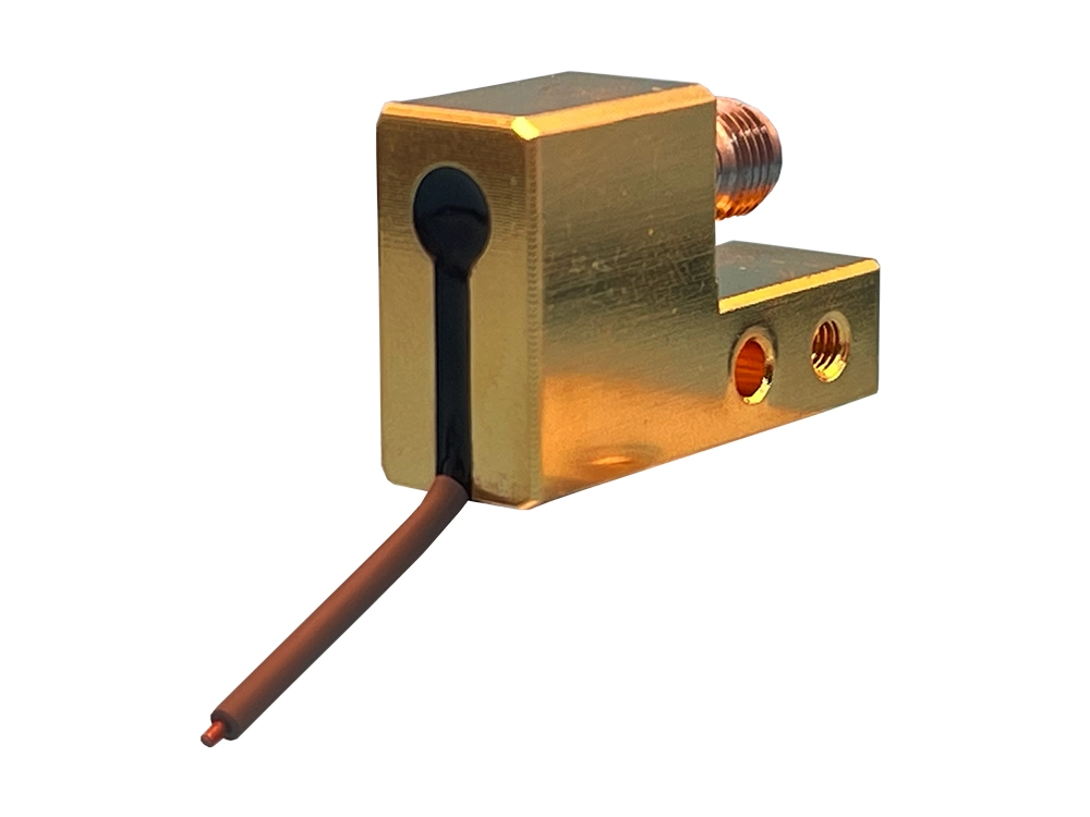
What makes cryogenic probing different
At extreme low temperatures, magnetic disturbance, thermal gradients, and mechanical repeatability become first-order error sources.
Magnetic cleanliness
Non-magnetic OFC construction supports superconducting measurements where ferromagnetic materials would distort local fields and undermine data integrity.
Thermal stability
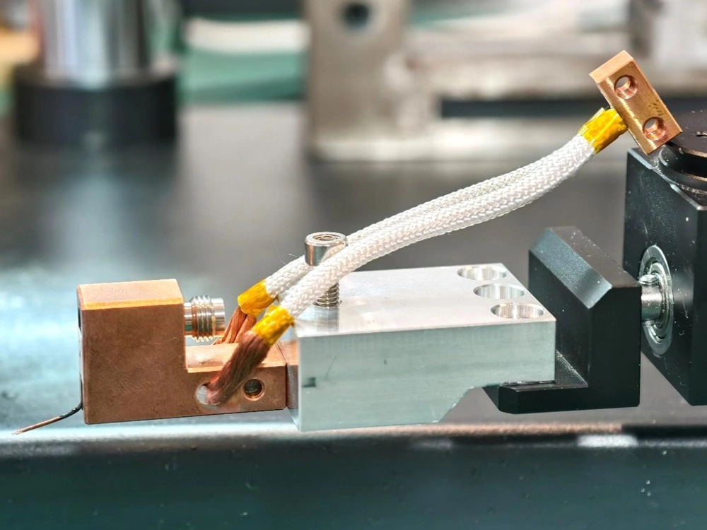
A strong thermal path through the copper body helps stabilize the probe and contact region through cool-down, soak, and measurement cycles.
Signal integrity
Controlled geometry supports < 1.0 dB insertion loss (40 GHz reference). Repeatable pad contact reduces reflections, protecting calibration confidence and extraction accuracy.
Configuration capabilities
Specify contact geometry first (GSG + pitch), then confirm interface requirements to fit your Device Under Test (DUT) and probe-station constraints.
GSG configuration
- •Ground–Signal–Ground (GSG) for controlled 50 Ω probing.
- •Standard tip size: 10 µm for precise pad contact.
- •Optimized to minimize field leakage and reflections at the pad transition.
50 to 1250 µm pitch
- •Pitch range: 50 µm to 1250 µm.
- •Standard pitch step: 50 µm.
- •Supports dense quantum pad arrays and larger calibration structures.
Interface & clearance
- •40 GHz reference uses a 2.92 mm interface.
- •45° angle improves clearance around radiation shields and optical paths.
- •For up to 67 GHz options, share probe-station constraints in the inquiry (configuration dependent).
Reference model & specifications
The table below reflects the validated 40 GHz reference configuration (series: VST-40G-GSG-XXX-MW/TU2). For higher-frequency options up to 67 GHz, share your probe-station constraints via inquiry (configuration dependent).
How to specify your build
Provide your probe station model, target band (40 / 67), and pad geometry. We map pitch + configuration to a verified, repeatable cryogenic probing setup.
-
1Choose tip geometry: GSG + pitch (50–1250 µm).
-
2Confirm band target: 40 GHz reference, or request up to 67 GHz (configuration dependent).
-
3Share pad notes: metallurgy + drawing/photo if available.
Technical specifications (40 GHz reference)
Download PDFTechnical FAQ
What is a cryogenic RF probe used for?
A cryogenic RF probe provides a controlled microwave transition to on-wafer pads in low-temperature setups, supporting superconducting device characterization, magnetically sensitive measurements, and quantum research where stability and repeatability matter.
Why choose a non-magnetic oxygen-free copper (OFC) probe?
Oxygen-free copper construction reduces the risk of magnetic interference from common metallic materials, helping preserve measurement integrity in superconducting and magnetically sensitive environments.
What frequency ranges are available for cryogenic GSG probes?
A 40 GHz reference configuration is validated on the VST-40G-GSG-XXX-MW/TU2 series. Options up to 67 GHz may be available by inquiry (configuration dependent) based on interface and probe-station constraints.
What pitch options are available for cryogenic GSG probes?
The pitch range is 50 µm to 1250 µm with a standard 50 µm step. Standard tip size is 10 µm for precise pad contact.
What information should I provide to request a quote?
Provide target frequency band, tip configuration (GSG), pitch (µm), probe station model, and quantity. Submit via the inquiry form and our team will verify fit for your setup.
If the inquiry form is blocked, how can I contact you?
Email sales@vinstronics.com with your target band, tip configuration, pitch, probe station model, and quantity, and we will respond with a verified configuration.
Ready to equip your probe station?
Submit your required pitch, band target (40 / 67), and quantity. Our engineering team will verify compatibility with your superconducting measurement setup.