
Precision Test Cables
Metrology-grade coaxial assemblies designed for stable, repeatable, and high-confidence RF measurements across laboratory, VNA, and production test paths. Choose the right build path by frequency band, routing environment, and protection level.
Need a faster recommendation? Send frequency, connector interfaces, and required length.
Built for Stable Measurements Under Real Routing Conditions
Test cables are part of the measurement path. They should help preserve calibration confidence when routing, movement, and handling become part of the setup.
Mechanical Phase Repeatability
Supports stable phase behavior during routing and handling in precision measurement setups.
Controlled Amplitude Variation
Helps reduce flexure-driven loss variation that can distort test interpretation.
Structure Choice for Real Environments
Choose standard or protected constructions based on whether the cable remains bench-routed or faces more handling.
Choose the Right Test Cable Path
Start with the required frequency band, then confirm whether the setup calls for standard routing flexibility or added mechanical protection.
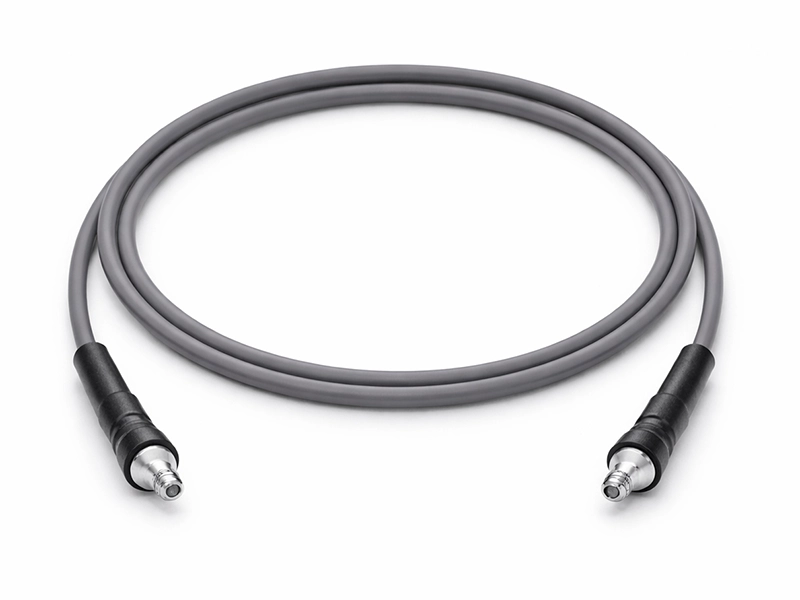
Millimeter-Wave Measurement
For 67 GHz and 110 GHz selection paths where the upper frequency limit is the primary filter.
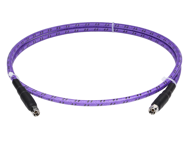
Microwave Laboratory & Validation
For 40 GHz and 50 GHz paths balancing precision measurement with practical routing flexibility.

Production, EMC & Field Test
For 18 GHz and 26.5 GHz paths where mechanical robustness and routing durability matter more.
Structure Options: Standard vs. KA/KB
Protected constructions are available when the setup includes more handling, movement, or external mechanical stress. KA uses stainless steel wire braiding for improved mechanical protection. KB adds spiral wrap support for more demanding torsion and handling conditions. For controlled bench and laboratory routing, the standard construction often remains the cleaner and more flexible choice.
Core Selection Matrix
Use this matrix to narrow the frequency path first, then confirm whether diameter and bend limits fit your routing environment.
| Short Code | Max Frequency | Outer Diameter | Static Bend Radius | Dynamic Bend Radius | Protected Option |
|---|---|---|---|---|---|
| T18 | 110 GHz | 1.85 mm | 10 mm | 20 mm | T18KA/KB |
| T24 | 67 GHz | 2.40 mm | 12 mm | 24 mm | T24KA/KB |
| T36 | 50 GHz | 3.60 mm | 18 mm | 36 mm | T36KA/KB |
| T42 | 40 GHz | 4.20 mm | 21 mm | 42 mm | T42KA/KB |
| T50 | 26.5 GHz | 5.10 mm | 25 mm | 50 mm | T50KA/KB |
| T80 | 18 GHz | 7.80 mm | 40 mm | 80 mm | T80KA/KB |
Engineering FAQ
What is a precision test cable?
How do I choose between standard and KA/KB structure?
What should I look at first?
Do I need KA/KB if the frequency code is the same?
Can final performance vary with connectors and cable length?
What is required for a quote?
Download Technical Guide
Download the technical guide for full dimensional data, attenuation references, K1/K2 constants, and model-level mechanical limits across standard and KA/KB builds.
Request Build Recommendation
Submit your target frequency, connector interfaces, structure preference, and required length. Our engineering team will recommend the most appropriate build path.