
High-Temperature Phase-Stable RF Cables
Phase-stable coaxial assemblies engineered for stationary RF routing in harsh thermal environments. Select the right cable path by frequency band, bend envelope, and thermal exposure profile.
Need a faster recommendation? Send frequency, target thermal profile, and required length.
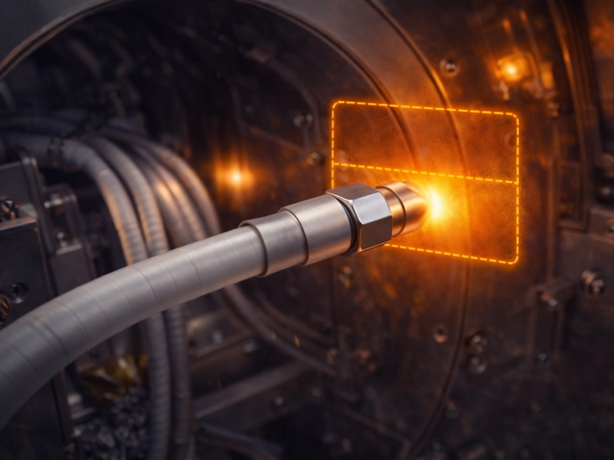
Built for Signal Integrity Under Severe Thermal Stress
High-temperature links require specialized material architectures to prevent dielectric degradation and phase shifting during heat exposure.
Short-Term Thermal Survivability
Engineered to withstand transient thermal peaks up to 400°C for 400 seconds without structural failure.
Stationary Phase Stability
Utilizes low-density PTFE (LD PTFE) dielectric to support stable phase behavior and low-loss transmission during thermal shifts.
Selection for Real Installation Constraints
Choose by frequency band, bend envelope, and thermal exposure rather than by generic cable size alone.
Choose the Right High-Temperature Cable Path
Start with the required frequency band, then select the physical footprint that matches your dimensional and mass routing constraints.
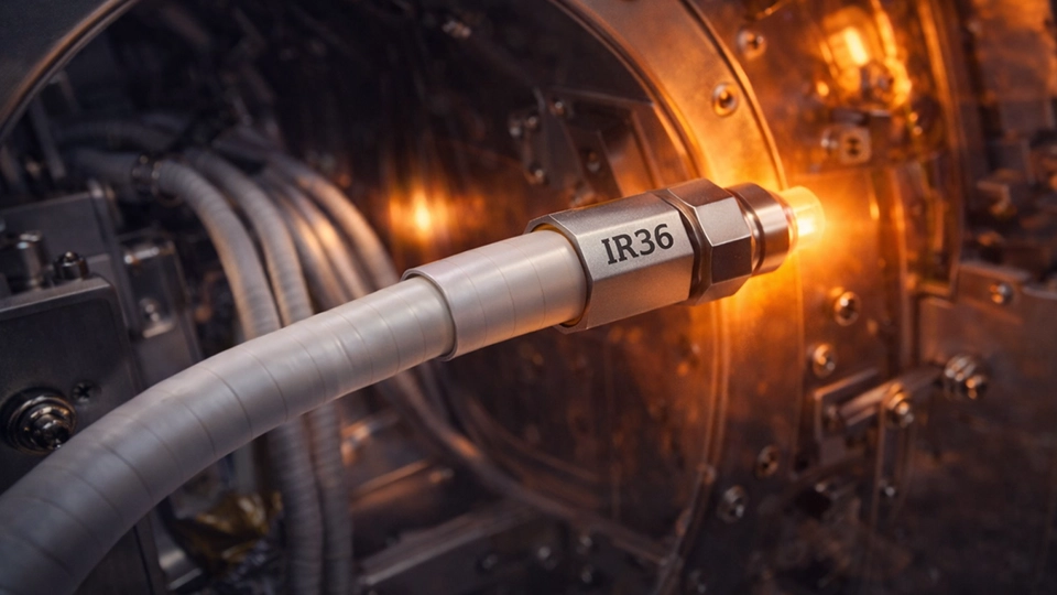
High-Density Thermal Test
Optimized for dense packaging and tight-space high-frequency routing up to 40 GHz.
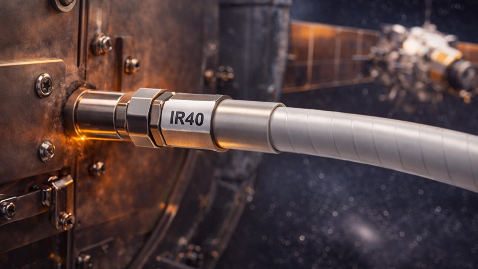
Versatile Harsh Environment
Provides an optimal midpoint between mechanical flexibility and 40 GHz electrical capability.
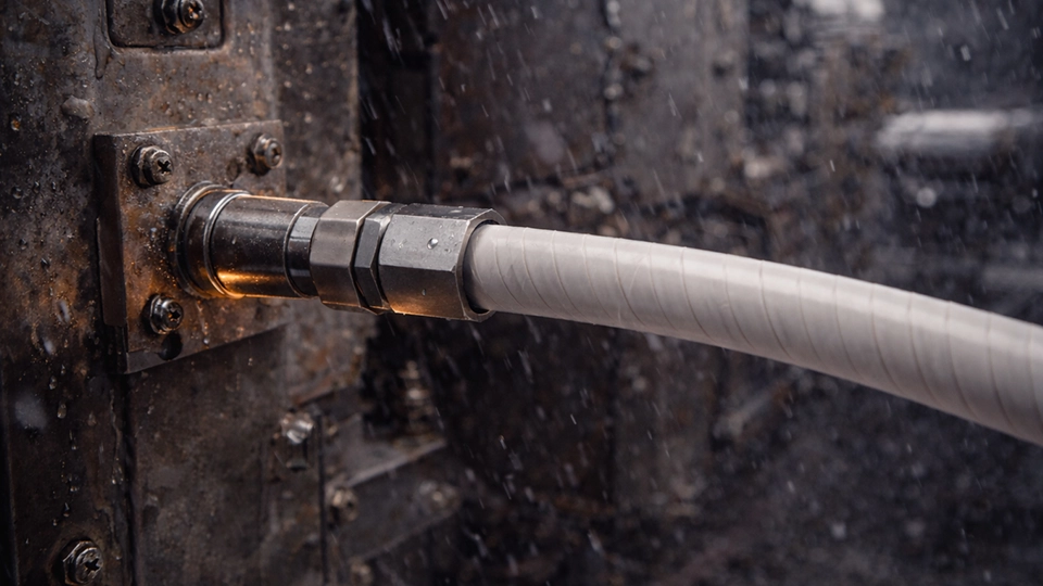
Lower-Frequency Robust Link
Larger cable format engineered to support rigorous signal integrity in applications up to 26.5 GHz.
Material Architecture: PI + PTFE Jacket System
The thermal endurance of this series relies on a specialized PI + PTFE outer jacket protecting the multi-layer silver-plated copper shielding and LD PTFE core. This specific material stack sustains mechanical baseline properties and preserves > 90 dB shielding effectiveness under severe ambient temperatures, preventing the rapid degradation seen in standard interconnects.
Core Selection Matrix
Use this matrix to narrow the frequency path first, then confirm whether diameter, bend limits, and thermal exposure fit your routing environment.
| Short Code | Max Frequency | Outer Diameter | Static Bend Radius | Dynamic Bend Radius | Operating Temperature | Short-Term Exposure |
|---|---|---|---|---|---|---|
| IR36 | 40 GHz | 3.60 mm | 18 mm | 36 mm | -55°C to +200°C | 400°C @ 400 s |
| IR40 | 40 GHz | 4.00 mm | 20 mm | 40 mm | -55°C to +200°C | 400°C @ 400 s |
| IR50 | 26.5 GHz | 5.40 mm | 27 mm | 54 mm | -55°C to +200°C | 400°C @ 400 s |
Engineering FAQ
What is a high-temperature phase-stable RF cable?
How is it different from a standard phase-stable RF cable?
How do I choose between IR36, IR40, and IR50?
Can the cable really withstand 400°C?
Are standard RF connectors suitable for high-temperature exposure?
What information is required for a quote?
Download Technical Guide
Download the technical guide for full attenuation references, thermal exposure profiles, dimensional limits, and model-level selection data across IR36, IR40, and IR50.
Request Build Recommendation
Submit your target frequency, expected thermal limits, connector interfaces, and required length. Our team will verify assembly feasibility. Final high-temperature capability depends on both cable construction and connector suitability.