
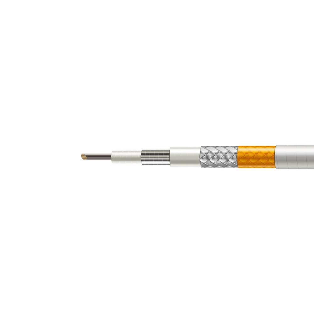
40 GHz Balanced High-Temperature Phase-Stable RF Cable IR40
P/N: IR40
– Balanced format for 40 GHz thermal paths
– 4.00 mm jacket supports practical routing
– Phase-stable cable for stationary assemblies
– Shielded path for harsh RF environments
– Built for high-temperature test setups
Engineering Note
The IR40 / VXIR400 is a balanced high-temperature phase-stable RF coaxial cable for 40 GHz stationary microwave paths that need a practical tradeoff between routing flexibility, attenuation, and thermal survivability. Compared with the more compact IR36, its 4.00 mm PI + PTFE jacket and 82% velocity support lower loss and higher average power while preserving confirmed 1000 VDC dielectric withstand voltage, >90 dB shielding effectiveness, and 400 °C / 400 s high-temperature endurance for thermal RF test setups, onboard links, and harsh-environment phase-sensitive assemblies.
Technical Specifications
| Cable Name | IR40 |
|---|---|
| Part No | VXIR400 |
| Product Type | High-temperature phase-stable RF coaxial cable |
| Cable Structure | 6-layer construction with silver-plated copper center conductor, LD PTFE dielectric, silver-plated copper tape inner shield, LD PTFE interlayer, silver-plated copper wire outer shield, and PI + PTFE outer jacket |
| Operating Frequency | 40 GHz |
| Cut-off Frequency | 56 GHz |
| Impedance | 50 Ω |
| Velocity of Propagation | 82% |
| Shielding Effectiveness | >90 dB |
| Dielectric Withstanding Voltage | 1000 VDC |
| Static Bending Radius | 20 mm |
| Dynamic Bending Radius | 40 mm |
| Weight | 0.029 kg/m |
| Storage Temperature | -55 °C to +125 °C |
| High-Temp Endurance | 400 °C @ 400 s |
| Center Conductor | Silver-plated copper, 0.91 mm |
| Dielectric | LD PTFE, 2.50 mm |
| Inner Shield | Silver-plated copper tape, 2.66 mm |
| Interlayer | LD PTFE, 2.95 mm |
| Outer Shield | Silver-plated copper wire, 3.35 mm |
| Outer Jacket | PI + PTFE, 4.00 mm |
| Outer Diameter | 4.00 mm |
Attenuation
| Frequency (MHz) | 1000 | 2000 | 3000 | 6000 | 8000 | 10000 | 12400 | 18000 | 26500 | 40000 |
|---|---|---|---|---|---|---|---|---|---|---|
| Attenuation (dB/100 m) | 41.2 | 58.6 | 72.0 | 102.9 | 119.4 | 134.0 | 149.9 | 182.3 | 223.8 | 279.1 |
Average Power
| Frequency (MHz) | 1000 | 2000 | 3000 | 6000 | 8000 | 10000 | 12400 | 18000 | 26500 | 40000 |
|---|---|---|---|---|---|---|---|---|---|---|
| Average Power (kW) | 0.509 | 0.358 | 0.291 | 0.204 | 0.176 | 0.156 | 0.140 | 0.115 | 0.094 | 0.075 |
Target Applications
Thermal RF Test Setups
40 GHz stationary test paths where high-temperature exposure, shielding, and practical routing flexibility must be kept in balance.
High-Temperature Onboard Links
Onboard RF paths exposed to elevated thermal stress where a 4.00 mm cable format gives more electrical margin than smaller formats.
Harsh-Environment Routing
Cable runs that need both manageable bending and thermal survivability inside demanding microwave systems.
Phase-Sensitive RF Assemblies
Stationary RF assemblies where phase-stable cable category, multilayer shielding, and 40 GHz operation support measurement continuity.

Engineering Support
Need a Quote or Technical Support?
Share the part number, required quantity and application requirements. Our engineering team can assist with product selection, configuration review and quotation support.
Product selection support
Custom configurations available
Specification and compatibility review