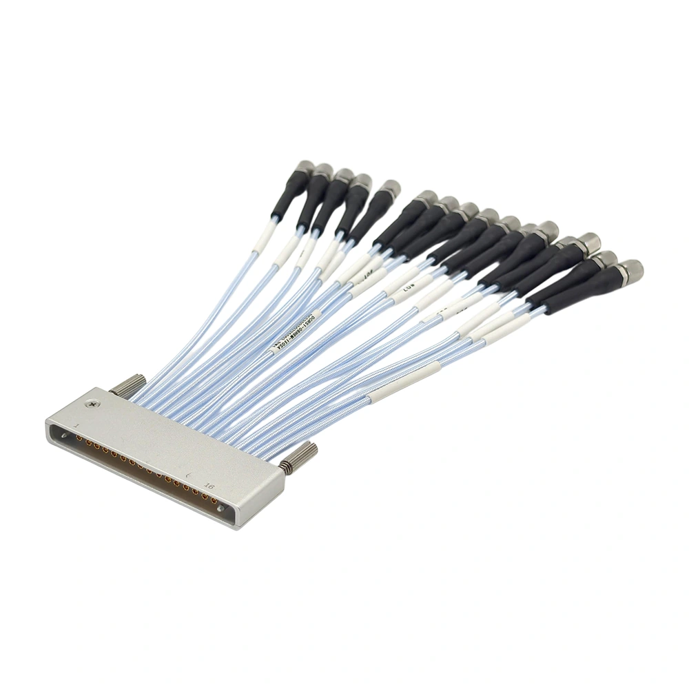
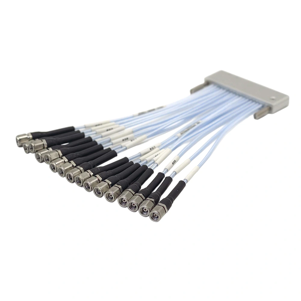
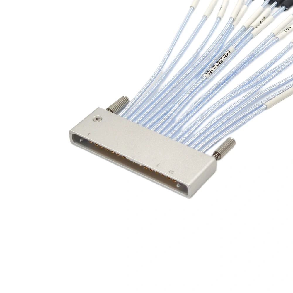
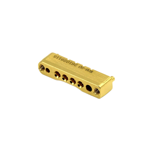
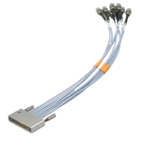
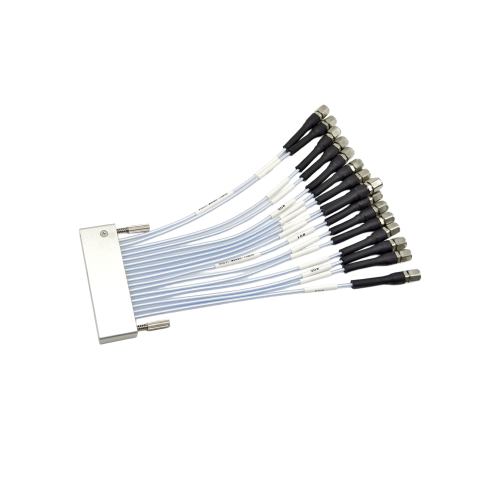
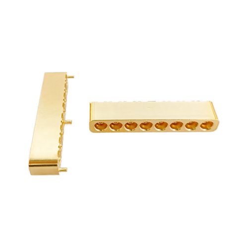
VST-L-TW90MF116-XXX is a 16-channel (1×16) high-density multi-coaxial breakout cable assembly that connects one TW90 multiport interface to 16 individual 1.0 mm male coaxial connectors. Designed for 50 Ω signal paths through 110 GHz, it enables grouped RF channels to connect to separate test-instrument and fixture ports.
Technical specifications
Electrical performance
Frequency range
DC–110 GHz
Nominal impedance
50 Ω per channel
Return loss
≥ 10 dB
Insertion loss
≤ (15 × L / 1000 + 1.8) dB (L = assembly length in mm)
Phase matching
±1 ps
Interface & mechanical specifications
Configuration
1 × 16 TW90 to 16 × 1.0 mm male
Multiport interface
TW90, single row
Contact pitch
2.54 mm
TW90 housing dimensions
55 × 16.5 × 6.82 mm (see drawing)
Mating durability
≥ 500 cycles
Minimum cable bend radius
18 mm
Cable length
Configurable; length tolerances in drawing
Construction & environment
TW90 housing
Anodized aluminum
Signal contacts
Gold-plated beryllium copper
Insulators
PTFE (TW90) / PEEK (1.0 mm end)
Operating temperature
0 °C to +85 °C
RoHS
Compliant (drawing)
Representative RF measurement
The datasheet includes representative system-level S11, S44 and S41 measurements from 10 MHz to 110 GHz using a TWS90J-16 PCB test board, mating connector and cable assembly. The reported S41 readings (−11.67 dB at 32.86 GHz and −17.03 dB at 109.99 GHz) describe the complete test path, not cable-only insertion loss.
Cable configuration & selection
Specify the required cable length and length reference, TW90 mating interface and mounting layout, channel-to-port assignment, and RF limits. Refer to the product drawing for mechanical dimensions, cable labeling and length tolerances. An RF test report is supplied with each assembly.
Share the part number, required quantity and application requirements.
Our engineering team can assist with product selection, configuration
review and quotation support.