
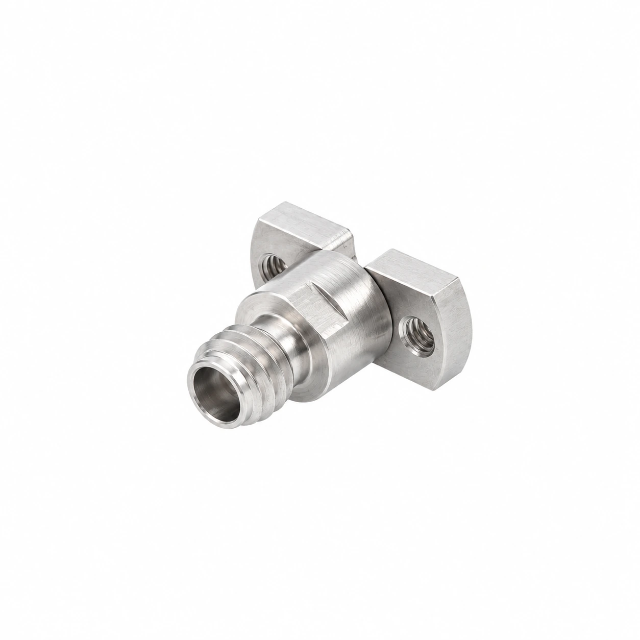
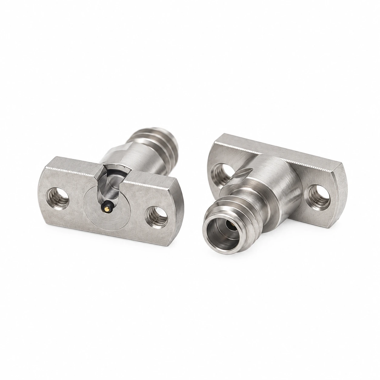
1.0 mm Solderless Vertical Launch PCB Connector, DC–110 GHz | VST-CPM10F-05
P/N: VST-CPM10F-05
• DC–110 GHz Precision PCB Interconnect
• Solderless 1.0 mm Female Vertical Launch | 50 Ω
• Return Loss ≥15 dB
• Two-Hole Screw-Mount Flange with Recommended PCB Layout
• Passivated Stainless-Steel Outer Conductor with Gold-Plated BeCu Center Contact
• Ø0.2 mm Recommended Signal Pad | 7.16 mm Mounting-Hole Spacing
VST-CPM10F-05 is a 50 Ω 1.0 mm female straight PCB connector for solderless vertical-launch integration from DC to 110 GHz. The two-hole screw-mount flange provides a defined mechanical interface to the PCB, while the supplied mechanical drawing includes the recommended PCB layout and launch geometry.
Electrical performance is specified at return loss ≥15 dB. The connector uses a passivated stainless-steel outer conductor, a gold-plated beryllium-copper center conductor, and a PEI dielectric.
DC–110 GHz Precision PCB Interconnect
Broadband 50 Ω interconnection for RF and millimeter-wave PCB test and integration through 110 GHz.
Solderless 1.0 mm Female Vertical Launch
Straight 1.0 mm female interface for direct vertical PCB integration without a soldered coaxial launch connection.
Return Loss ≥15 dB
Specified return loss of at least 15 dB across the rated DC–110 GHz frequency range.
Two-Hole Screw-Mount Flange
Two M1.6 mounting locations provide a defined mechanical attachment to the PCB assembly.
Recommended PCB Layout Provided
The mechanical drawing includes the recommended board layout and detailed launch geometry for integration review.
Precision Metal & Contact Construction
Passivated stainless-steel outer conductor with a gold-plated BeCu center conductor and PEI dielectric.
| Part Number | VST-CPM10F-05 |
|---|---|
| Connector Type | 1.0 mm Female, Straight PCB Connector |
| Impedance | 50 Ω |
| Frequency Range | DC–110 GHz |
| Return Loss | ≥15 dB |
| Dielectric Withstand Voltage | 500 Vrms |
| Insulation Resistance | 5000 MΩ |
The supplied mechanical drawing includes a Recommended PCB Layout with the flange outline, mounting-hole locations, center launch region, and Detail B dimensions.
Key references shown on the drawing include 7.16 mm mounting-hole center spacing, 2 × M1.6 connector mounting threads, 2 × Ø1.6 +0.05 mm PCB mounting holes, and a Ø0.2 mm recommended signal pad. Use the drawing as the dimensional authority for board implementation.
| Interface Thread | M4 × 0.7 |
|---|---|
| Mounting Threads | 2 × M1.6 |
| Mounting-Hole Center Spacing | 7.16 mm |
| Overall Axial Length | 9.45 mm |
| Mounting Body Width (Front View) | 4.57 mm |
| Recommended Signal Pad | Ø0.2 mm |
| Outer Conductor | Stainless steel, passivated |
| Center Conductor | Beryllium copper, gold-plated |
| Dielectric | PEI |
| Screw | Stainless steel, passivated |
110 GHz PCB Test Fixtures
Precision coaxial access for high-frequency fixtures and PCB-based measurement structures.
Millimeter-Wave Evaluation Boards
Board-level RF connectivity for devices, modules, and test vehicles operating through 110 GHz.
VNA & Component Characterization
High-frequency interface between compatible 1.0 mm test cables and PCB measurement structures.
RF & mmWave R&D
Compact PCB interconnection for laboratory development and characterization setups.
The recommended PCB layout is included in the mechanical drawing. For a 110 GHz solderless vertical-launch implementation, use the drawing dimensions as the mechanical reference and review the complete PCB stack-up and transition geometry as part of the board-level RF design.
Integrate a 1.0 mm Solderless Vertical Launch into Your 110 GHz Design
Share your PCB stack-up, board thickness, launch geometry, and test requirements for connector selection or technical review.


Need a Quote or Technical Support?
Share the part number, required quantity and application requirements. Our engineering team can assist with product selection, configuration review and quotation support.