
Phase- and amplitude-stable precision test interconnects for VNA, microwave and mmWave measurement paths from DC to 110 GHz.
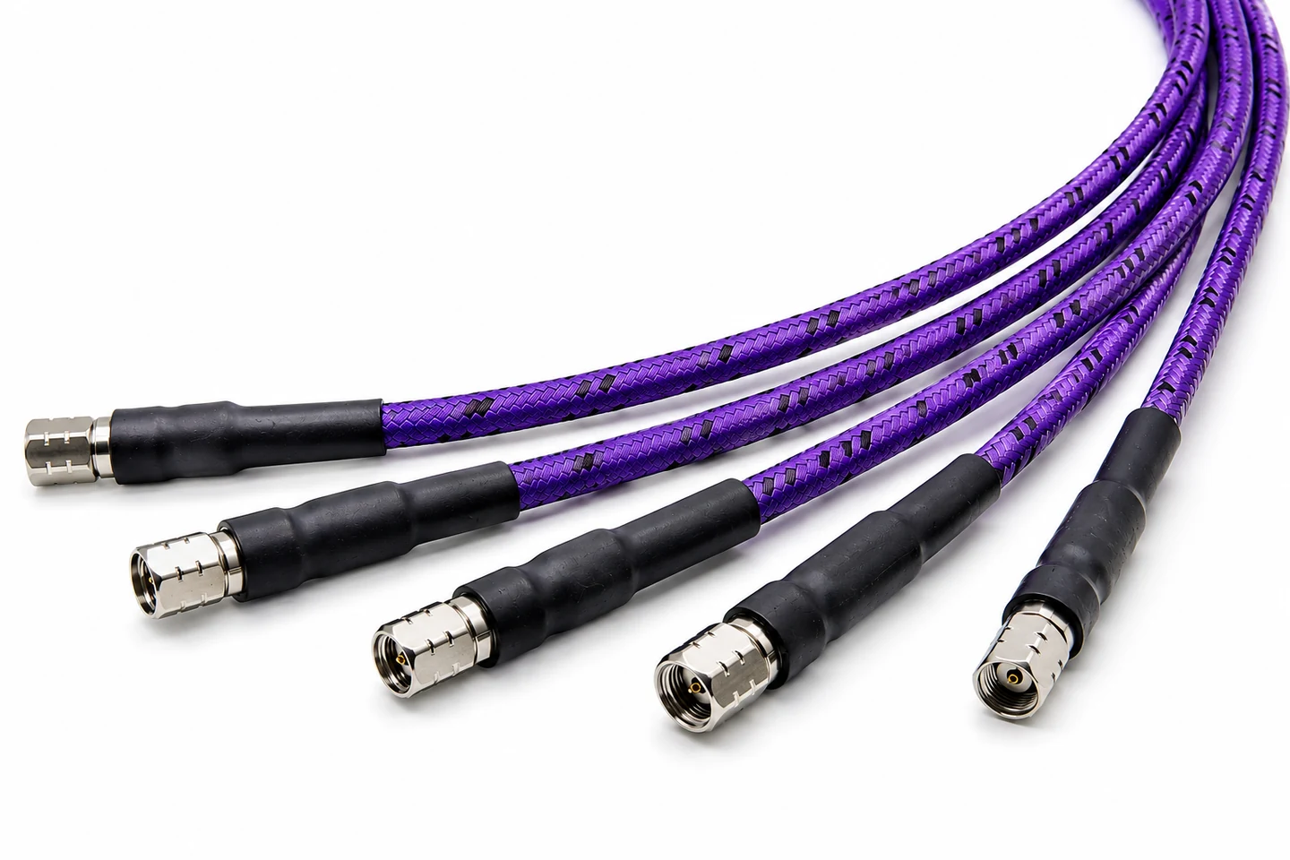
Why Armored Test Cables?
Stable RF measurements require a test cable that maintains electrical performance as it is repositioned, routed and repeatedly handled.
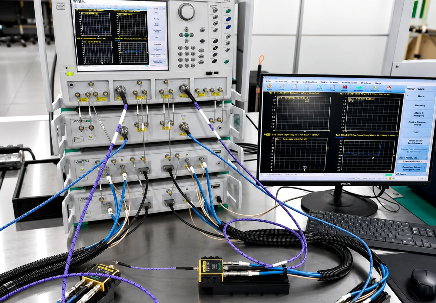
Phase Stability with Flexure
Controls electrical-length variation as the cable is moved.
Amplitude Stability with Flexure
Limits transmission variation during repositioning and repeated handling.
Integrated Mechanical Protection
Armored construction protects the RF transmission core in demanding test environments.
Individual RF Verification
Every completed assembly is RF tested and supplied with its corresponding measurement report.
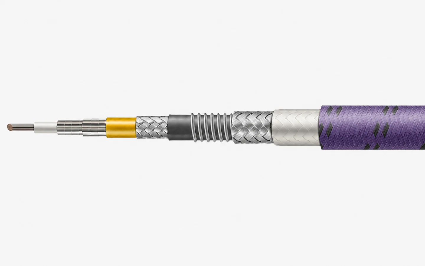
T26KB Integrated Armored RF Test Cable
A precision RF coaxial core with four additional integrated protection layers.
Cable Platforms from 18 to 110 GHz
Choose the platform around the required bandwidth, routing constraints and measurement setup.
| Platform | Max. Frequency | Cable OD |
|---|---|---|
| T80KA / KB | 18 GHz | 10.40 mm |
| T50KA / KB | 26.5 GHz | 7.60 mm |
| T42KA / KB | 40 GHz | 6.70 mm |
| T36KA / KB | 50 GHz | 6.10 mm |
| T26KBFeatured 67 GHz | 67 GHz | 4.95 mm |
| T18KA / KB | 110 GHz | 3.84 mm |
Representative Armored Test Cable Assemblies
Representative configurations by interface and bandwidth. Cable platform, length and phase-matched pairs can be configured to the measurement setup.

1.0 mm Male-to-Male Integrated Armored RF Test Cable Assembly
DC–110 GHz with precision 1.0 mm male interfaces for W-band and mmWave measurement paths.
View 110 GHz Product →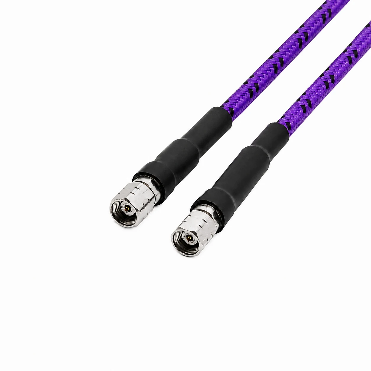
1.85 mm Male-to-Male Integrated Armored RF Test Cable Assembly
DC–67 GHz with precision 1.85 mm male interfaces for VNA and mmWave measurement.
View 67 GHz Product →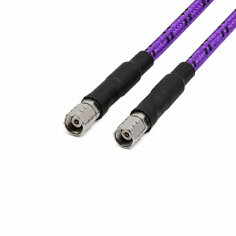
2.4 mm Male-to-Male Integrated Armored RF Test Cable Assembly
DC–50 GHz with precision 2.4 mm male interfaces for microwave and mmWave test.
View 50 GHz Product →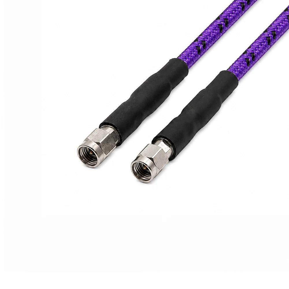
2.92 mm Male-to-Male Integrated Armored RF Test Cable Assembly
DC–40 GHz with precision 2.92 mm male interfaces for broadband microwave test.
View 40 GHz Product →Available for paired armored RF test cable assemblies when specified at order stage.
Every Finished Assembly Is Individually RF Tested
Every completed armored RF test cable assembly is RF tested before shipment and supplied with its corresponding measurement report.
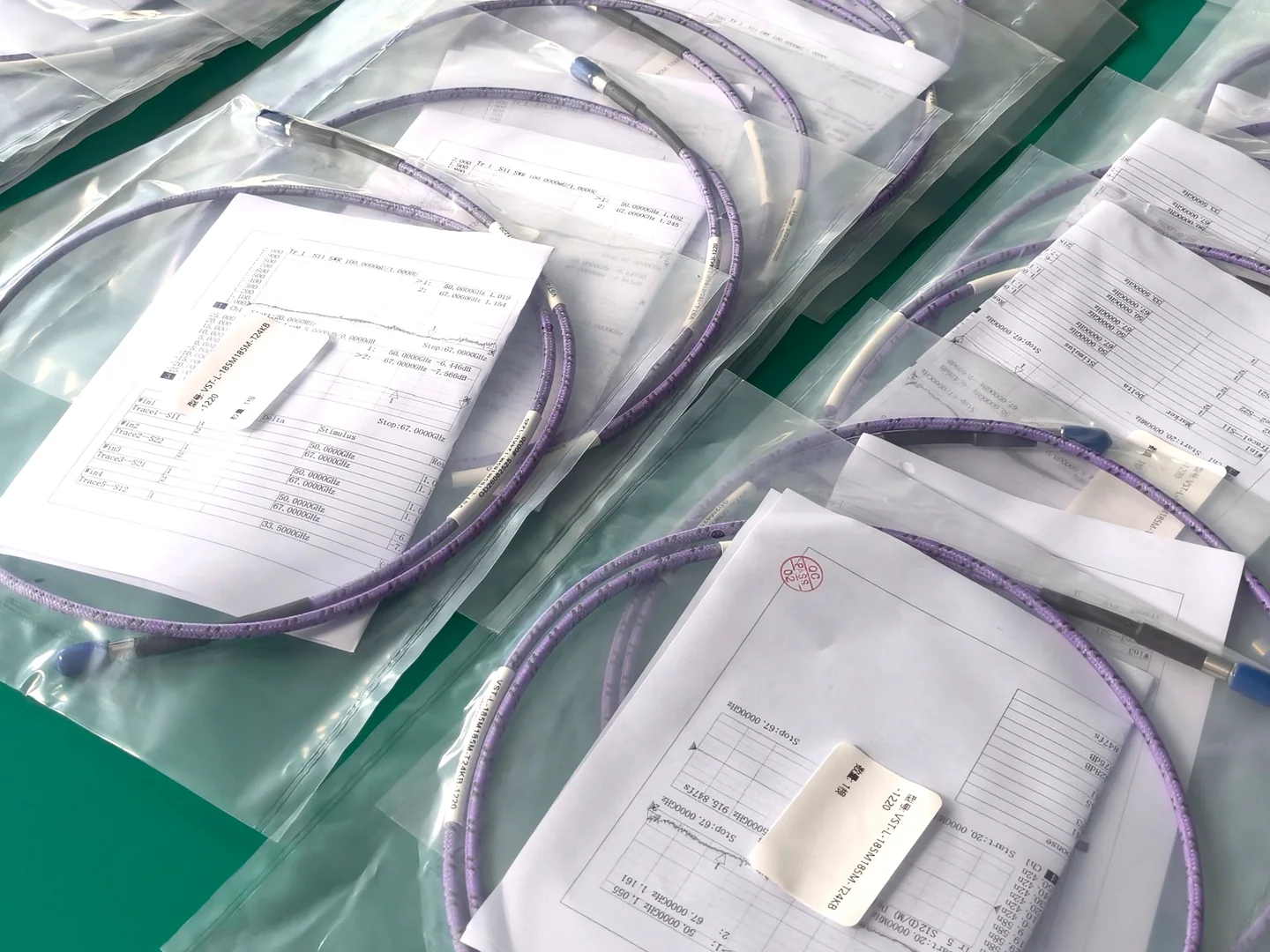
Completed-assembly S-parameter verification
Verification is performed on the completed connectorized assembly.
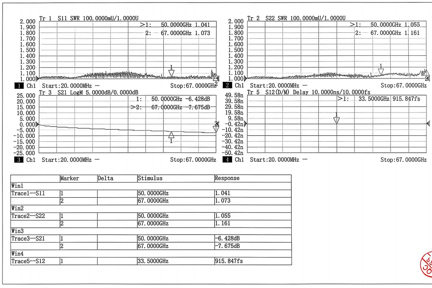
Representative measurement shown. Actual performance depends on cable platform, assembly length, connector interfaces and completed configuration.
Typical Test Environments
Typical environments for precision RF, microwave and mmWave test interconnects.
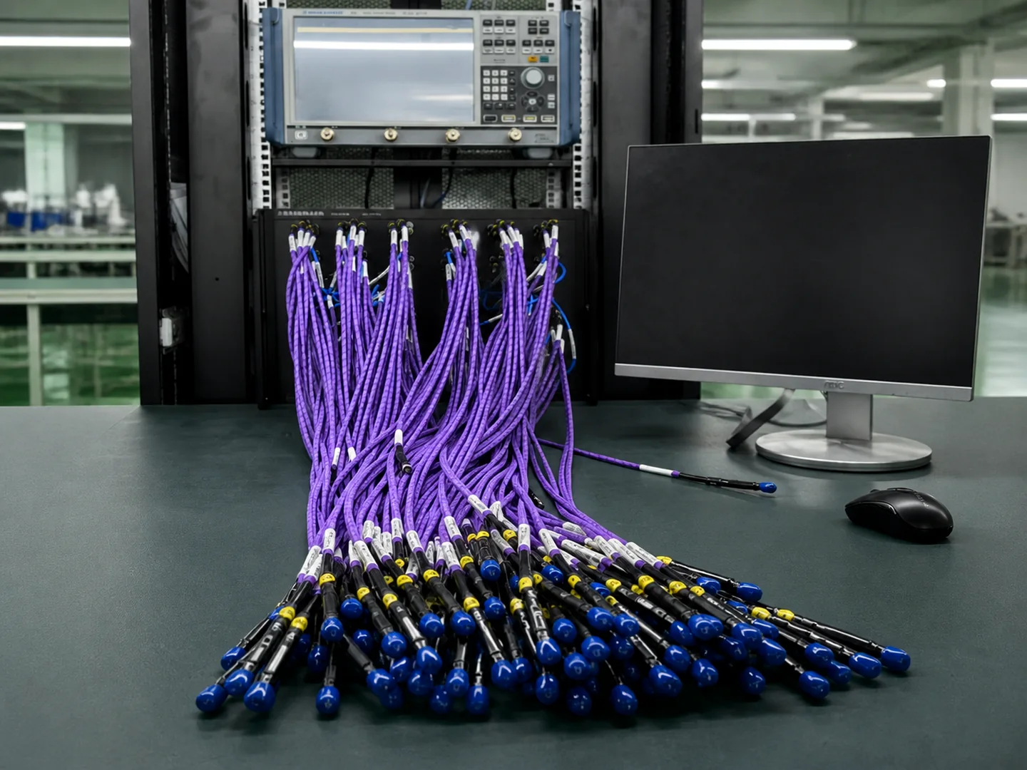
VNA & Laboratory Measurement
Precision RF and microwave characterization of components, fixtures and interconnects.
Production RF Test
Repeated DUT connection and cable handling in manufacturing and automated test stations.
Microwave & mmWave R&D
High-frequency development where cable movement can affect measurement repeatability.
System & Field Measurement
Protected RF interconnects for portable instrumentation and integrated test systems.
Common Selection Questions
Start with the measurement requirement rather than trying to decode a part number first.
How do I choose the cable platform?
Start with required bandwidth, attenuation, bend radius and routing conditions.
Does cable-platform frequency equal final assembly bandwidth?
No. Final usable bandwidth also depends on the connector interfaces and the complete connectorized assembly.
What information should I send for selection?
Frequency range, Connector A, Connector B, assembly length, routing condition and quantity are useful starting points.
Is every finished assembly supplied with a report?
Yes. Each completed armored RF test cable assembly is RF tested before shipment and supplied with its corresponding measurement report.
Engineering Review for Armored RF Test Cable Selection
Send your measurement requirements and Vinstronics will review the appropriate cable platform, connector interfaces and finished assembly configuration.