
Single-ended RF probing for restricted pad layouts, compact PCB structures and wafer characterization from DC to 110 GHz.
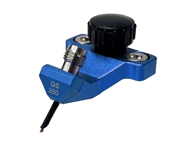
GS vs SG — when to use this configuration
GS and SG probes use the same single-ended two-contact topology. The difference is the Ground / Signal tip orientation required by the DUT pad layout.
Confirm the required GS / SG orientation against the product drawing and DUT pad layout before ordering.
Use GS / SG when the available pad geometry cannot accommodate a three-contact GSG footprint.
Suitable when the DUT test point provides one signal pad and one adjacent ground pad.
Useful for board-level validation where mechanical access around the RF pad is limited.
Suitable for non-differential DUT pads where one signal contact and one adjacent ground contact are required.
GS / SG models by frequency
Choose the required bandwidth first, then confirm tip option, pad pitch and RF interface against the DUT layout.

40 GHz GS / SG
Single-ended probing for general PCB validation, bias-line access and wafer-level RF characterization.
67 GHz GS / SG
Higher-frequency single-ended probing for compact mmWave structures, PCB validation and wafer test.
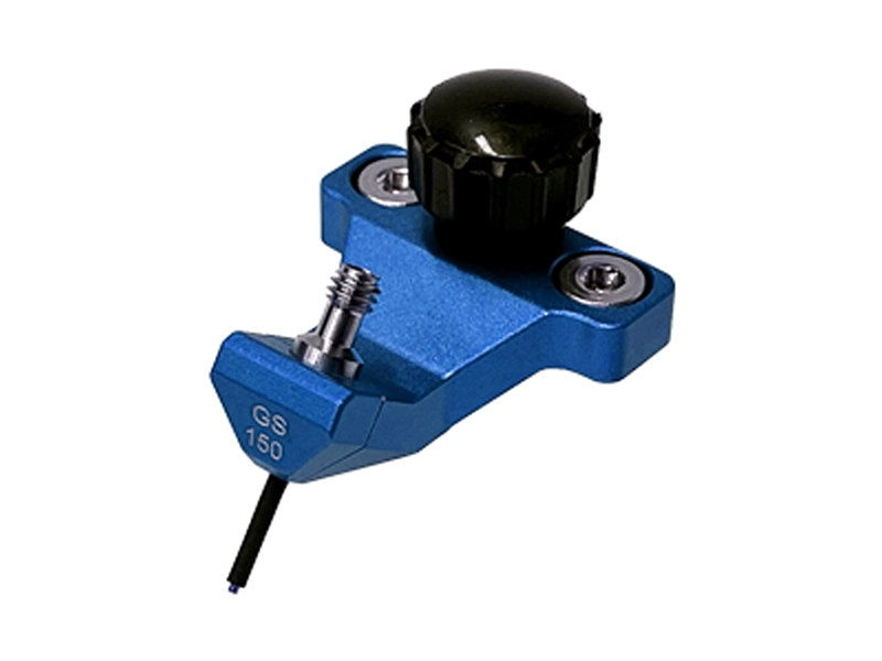
110 GHz GS / SG
Precision single-ended probing for advanced mmWave PCB structures and wafer-level characterization.
GS / SG model selection
Compare the current GS / SG base models by frequency, pitch, tip radius and RF interface. LYRA and AQUILA are shown as series identifiers for standard-tip and fine-tip variants.
| Model / Series | Frequency | Pitch Range | Tip Radius | Connector | Action |
|---|---|---|---|---|---|
| VST-40G-GS-XXX LYRA | DC–40 GHz | 100–1250 µm | 25 / 50 µm | 2.92 mm (K) Female | |
| VST-67G-GS-XXX LYRA | DC–67 GHz | 100–1250 µm | 25 / 50 µm | 1.85 mm (V) Female | |
| VST-110G-GS-XXX LYRA | DC–110 GHz | 100–1250 µm | 25 / 50 µm | 1.00 mm (W) Female | |
| VST-40G-GS-XXX-LF AQUILA | DC–40 GHz | 100–1250 µm | 10 µm | 2.92 mm (K) Female | |
| VST-67G-GS-XXX-LF AQUILA | DC–67 GHz | 100–1250 µm | 10 µm | 1.85 mm (V) Female | |
| VST-110G-GS-XXX-LF AQUILA | DC–110 GHz | 40–1250 µm | 10 µm | 1.00 mm (W) Female |
Specify the required GS or SG orientation when requesting a quote. Replace “XXX” with the required pad pitch. Custom pitch options are subject to model and DUT geometry; confirm non-standard requirements against the current Selection Guide or project drawing.
RF Probe Selection Guide
Use the current guide for detailed GS / SG model coverage, pitch options, fine-tip configurations, probe cards and calibration-substrate reference.
GS / SG Selection Questions
What is the difference between GS and SG?
GS and SG use the same single-ended two-contact topology. The difference is the Ground / Signal tip orientation required by the DUT pad layout.
When should I choose GS / SG instead of GSG?
Choose GS / SG when the pad layout or mechanical access cannot accommodate a three-contact GSG footprint, or when the test point uses a two-contact signal-and-ground arrangement.
How should I specify GS / SG probe pitch?
Specify the center-to-center spacing of the Ground and Signal pads together with the required GS or SG orientation. Pitch availability depends on the selected model and tip option.
What information is needed for model selection?
Provide the required orientation, frequency range, DUT pad layout and pitch. A drawing or close-up image is recommended for non-standard geometries.
Engineering Review for GS / SG Probe Selection
Send the required orientation, frequency range and DUT pad layout. Vinstronics can review pitch, tip option and model suitability before quotation.