
Single-ended Ground–Signal–Ground probing for CPW structures, wafer devices and PCB characterization from DC to 145 GHz.
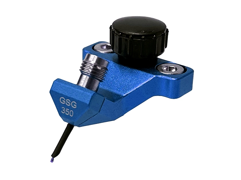
When to use a GSG probe
GSG probes use a Ground–Signal–Ground three-contact layout for single-ended RF measurements. The probe contact order and pitch must match the DUT pad geometry.
Confirm the G–S–G pad order and center-to-center pitch against the DUT drawing before ordering.
Use GSG when the DUT provides a signal pad with adjacent ground contacts on both sides.
Suitable for calibrated RF and mmWave characterization of single-ended DUT structures.
Applicable to wafer devices, RF launches, components and high-frequency PCB structures.
Available with 2.92, 1.85, 1.00 and 0.8 mm female interfaces across the current frequency platforms.
GSG models by frequency
Choose the required bandwidth first, then confirm pitch, tip variant and RF interface against the DUT layout and measurement setup.

40 GHz GSG
General-purpose GSG probing for PCB RF structures, wafer devices and component characterization.
67 GHz GSG
Higher-frequency GSG probing for mmWave PCB structures, components and wafer characterization.

110 GHz GSG
Precision GSG probing for W-band and advanced mmWave PCB and wafer characterization.
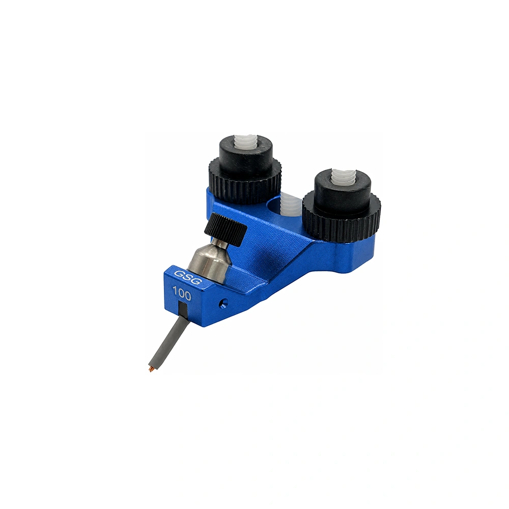
145 GHz GSG
LYRA D-band GSG model for device and interconnect characterization through 145 GHz.
GSG model selection
Compare the current core, specialty and fine-tip GSG models. LYRA and AQUILA are retained as series identifiers, while specialty labels highlight application-specific variants.
| Model / Series | Frequency | Pitch Range | Tip Radius | Connector | Action |
|---|---|---|---|---|---|
| Core Frequency Models | |||||
| VST-40G-GSG-XXXLYRA | DC–40 GHz | 100–1250 µm | 25 / 50 µm | 2.92 mm (K) Female | |
| VST-67G-GSG-XXXLYRA | DC–67 GHz | 100–1250 µm | 25 / 50 µm | 1.85 mm (V) Female | |
| VST-110G-GSG-XXXLYRA | DC–110 GHz | 100–1250 µm | 25 / 50 µm | 1.00 mm (W) Female | |
| VST-145G-GSG-XXXLYRAD-BAND | DC–145 GHz | 100–1250 µm | See drawing | 0.8 mm Female | |
| Specialty & Fine-Tip Variants | |||||
| VST-40G-GSG-XXX-LLLYRALOW LOSS | DC–40 GHz | 100–1250 µm | 25 / 50 µm | 2.92 mm (K) Female | |
| VST-40G-GSG-XXX-MW/TU2LYRANON-MAGNETIC | DC–40 GHz | 100–1250 µm | 25 / 50 µm | 2.92 mm (K) Female | |
| VST-40G-GSG-XXX-SHLYRASLIM BODY | DC–40 GHz | 100–1250 µm | 25 / 50 µm | 2.92 mm (K) Female | |
| VST-40G-GSG-XXX-LFAQUILA | DC–40 GHz | 100–1250 µm | 10 µm | 2.92 mm (K) Female | |
| VST-67G-GSG-XXX-LFAQUILA | DC–67 GHz | 100–1250 µm | 10 µm | 1.85 mm (V) Female | |
| VST-110G-GSG-XXX-LFAQUILA | DC–110 GHz | 100–1250 µm | 10 µm | 1.00 mm (W) Female | |
Replace “XXX” with the required G–S–G pad pitch. Custom pitch options are subject to model and DUT geometry. For 145 GHz and specialty variants, confirm the current drawing and Selection Guide before ordering.
RF Probe Selection Guide
Use the current guide for detailed GSG model coverage, pitch and tip options, specialty variants, probe cards and calibration-substrate reference.
GSG Selection Questions
When should I choose a GSG probe?
Choose GSG when the DUT pad order is Ground–Signal–Ground and the measurement requires a single-ended RF contact with local ground contacts on both sides of the signal pad.
How should I specify GSG probe pitch?
Specify the center-to-center spacing of the DUT Ground–Signal–Ground pads together with the target frequency and pad layout drawing.
Which connector is used for each frequency platform?
Standard GSG models use 2.92 mm Female at 40 GHz, 1.85 mm Female at 67 GHz, 1.00 mm Female at 110 GHz and 0.8 mm Female at 145 GHz.
What information is needed for GSG model selection?
Provide the target frequency, GSG pad pitch, DUT pad layout and DUT type. A drawing or close-up image is recommended for non-standard geometries.
Engineering Review for GSG Probe Selection
Send the target frequency and DUT G–S–G pad layout. Vinstronics can review pitch, tip variant, RF interface and model suitability before quotation.