Product overview
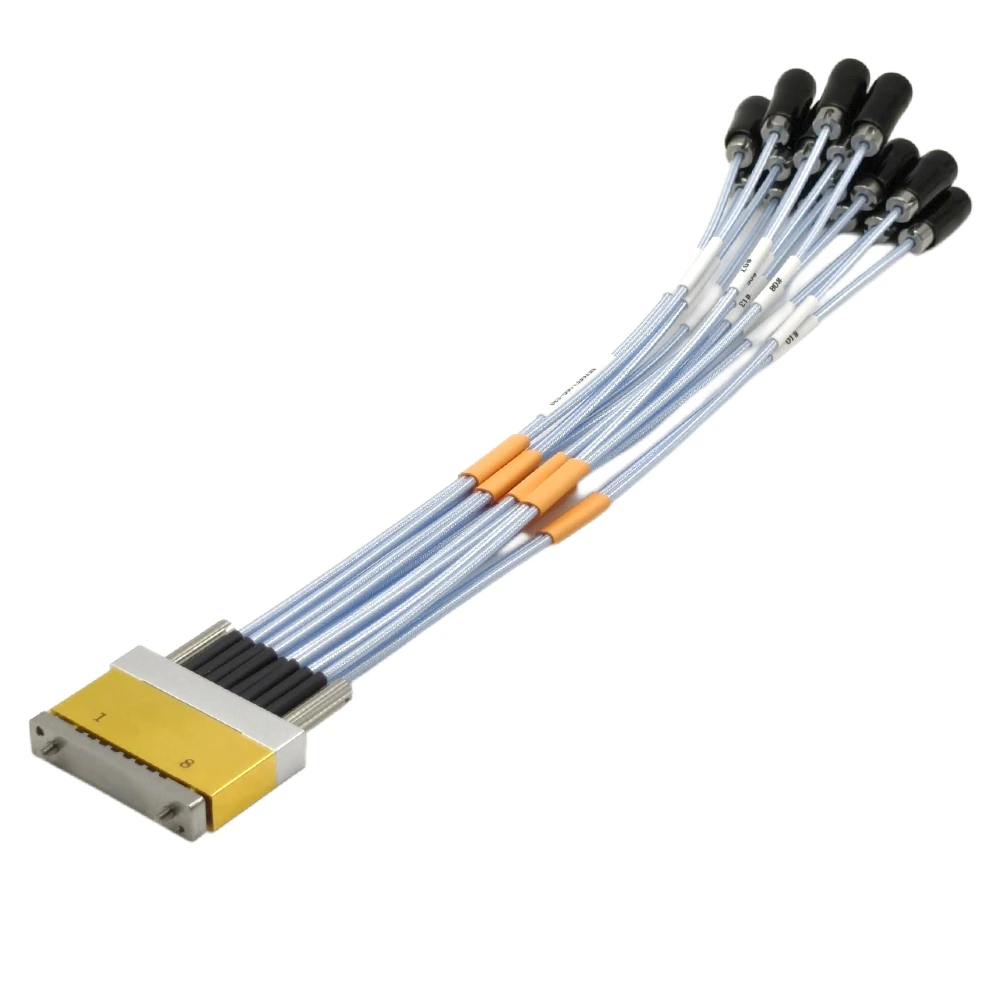
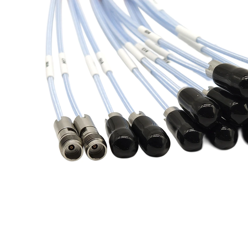
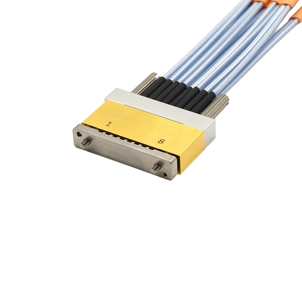
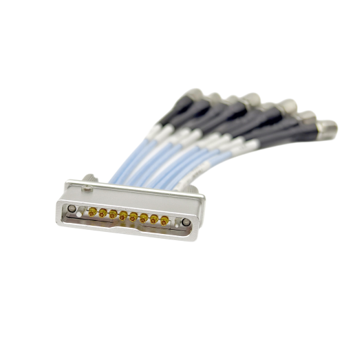
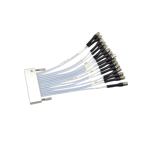
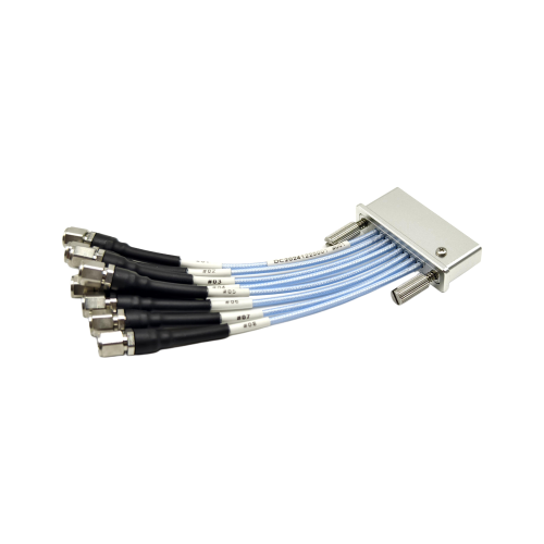
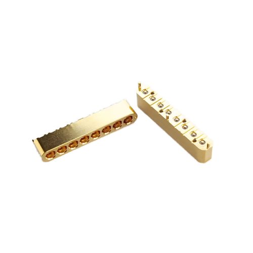
VST-TE70FF116C-XXX is a 16-channel high-density multi-coax breakout cable assembly operating from DC to 67 GHz. Its 2×8 TE70 interface connects to 16 individual 1.85 mm female breakout ports for board-level and multi-channel RF test connections.
Technical specifications
| Configuration & interfaces |
| Channel count |
16 coaxial channels |
| Multi-coax interface |
TE70, 2×8 configuration |
| Breakout interfaces |
16 × 1.85 mm female |
| Channel pitch |
2.54 mm |
| Cable assembly length |
Custom length, specified in mm |
| Electrical performance |
| Frequency range |
DC–67 GHz |
| Nominal impedance |
50 Ω per coaxial channel |
| Return loss |
≥ 10 dB |
| Insertion loss |
≤ (11.5 × L / 1000) + 1.2 dB (L = assembly length in mm) |
| Phase matching |
±2 ps |
| Test voltage |
300 Vrms |
| Mechanical & environmental specifications |
| Mechanical life |
≥ 500 cycles |
| Operating temperature |
0 °C to +85 °C |
| RoHS |
Compliant |
| Materials & finishes |
| TE70 shell |
Aluminum, anodized |
| TE70 center contact |
Beryllium copper, gold plated |
| TE70 outer contact |
Beryllium copper, gold plated |
| TE70 insulator |
PEEK |
| 1.85 mm center contact |
Beryllium copper, gold plated |
| 1.85 mm outer contact |
Stainless steel, passivated |
| 1.85 mm insulator |
PEI |
| Other metallic parts |
Stainless steel, passivated |
Test data
The datasheet includes representative mixed-mode measurements from 10 MHz to 67 GHz: Sdd11 / Sdd22 for differential return loss and Sdd21 / Sdd12 for differential insertion loss. These results apply to the tested assembly and configuration; actual performance varies with cable length and configuration. Individual test data are available on request.
Configuration & PCB integration
Specify the required assembly length, channel mapping and phase-matching requirements for the test setup. Verify the TE70 mating interface, mounting features and recommended PCB layout against the product drawing before board integration.