
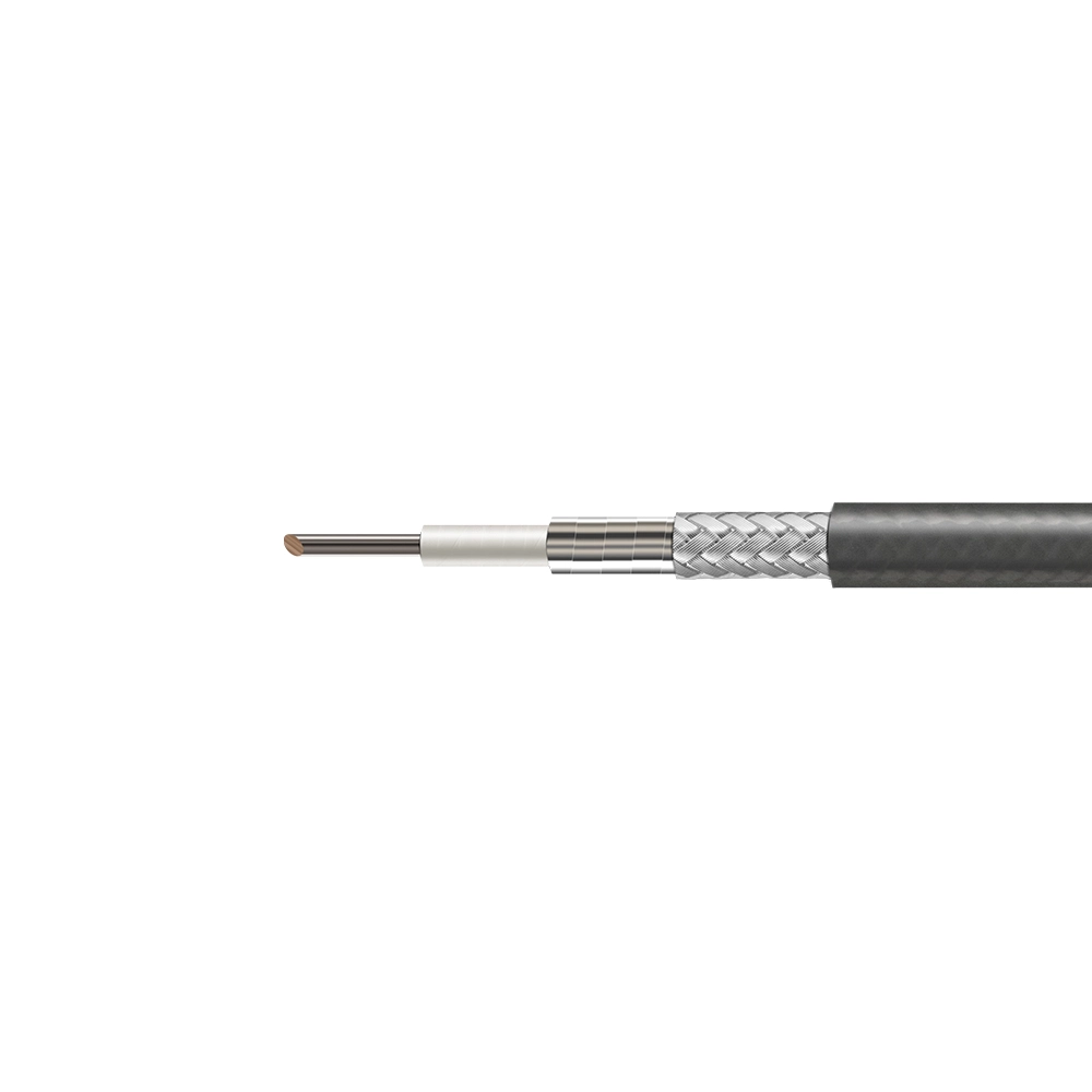
10 GHz Mega-Size Extreme-Voltage Ultra-Low-Loss Phase-Stable RF Cable W100
P/N: W100
- Mega-size cable for extreme power routing
- 3000 V.DC structure for high-voltage systems
- Ultra-low-loss path for 10 GHz transmission
- Phase-stable routing for critical radar systems
- Built for naval and ground-based platforms
Engineering Note
The W100 is a 10 GHz mega-size extreme-voltage ultra-low-loss phase-stable flexible RF coaxial cable designed for high-power microwave interconnects, ground-based radar, naval radar, avionics systems, and extreme power routing where phase consistency, voltage withstand, low insertion loss, and large-diameter cable durability are required. Its 10.00 mm gray FEP mega-size jacket provides a robust protective outer layer for demanding installations, while the LD PTFE dielectric, silver-plated copper inner conductor, silver-plated copper strip inner shield, and silver-plated copper braid outer shield support stable microwave signal transmission. The cable combines DC–10 GHz operating capability, <750 PPM phase stability, 3000 V.DC dielectric withstand voltage, -155 dBc low PIM performance, >90 dB shielding effectiveness, and 36.1 dB/100m attenuation at 10 GHz for extreme-voltage phase-critical RF interconnect applications.
Technical Specifications
| Cable Name | W100 |
|---|---|
| Product Type | Mega-Size Extreme-Voltage Ultra-Low-Loss Phase-Stable Flexible RF Coaxial Cable |
| Cable Structure | 5-layer phase-stable RF cable with mega-size gray FEP jacket |
| Operating Frequency | DC–10 GHz |
| Cut-off Frequency | 13.5 GHz |
| Impedance | 50 ± 1 Ω |
| Velocity of Propagation | 83% |
| Shielding Effectiveness | >90 dB |
| Phase Stability | <750 PPM @ -55 °C to +85 °C |
| Low PIM Performance | -155 dBc |
| Dielectric Withstanding Voltage | 3000 V.DC |
| Static Bending Radius | 41 mm [1.614 in] |
| Dynamic Bending Radius | 83 mm [3.268 in] |
| Weight | 0.206 kg/m [0.1384 lbs/ft] |
| Temperature Range | -55 to +105 °C [-67 to +221 °F] |
| Inner Conductor | Silver-plated copper, 3.00 mm [0.118 in] |
| Dielectric | Low Density PTFE, 8.24 mm [0.324 in] |
| Inner Shield | Silver-plated copper strip, diameter not specified |
| Outer Shield | Silver-plated copper wire braiding, 9.20 mm [0.362 in] |
| Jacket | FEP / Gray, customizable, 10.00 mm [0.394 in] |
| Attenuation | 10.4 dB/100m @1 GHz; 15.0 dB/100m @2 GHz; 18.7 dB/100m @3 GHz; 21.8 dB/100m @4 GHz; 24.6 dB/100m @5 GHz; 27.2 dB/100m @6 GHz; 31.9 dB/100m @8 GHz; 36.1 dB/100m @10 GHz |
| Average Power | 2.289 kW @1 GHz; 1.590 kW @2 GHz; 1.281 kW @3 GHz; 1.097 kW @4 GHz; 0.972 kW @5 GHz; 0.880 kW @6 GHz; 0.750 kW @8 GHz; 0.662 kW @10 GHz |
Target Applications
Ground-Based Radar
Suitable for ground radar systems requiring extreme-voltage capability, phase stability, and high-power RF transmission.
Naval Radar Systems
Supports naval RF platforms where rugged cable construction, stable phase, and high-voltage routing are required.
Extreme Power Routing
Used for high-power microwave paths where low attenuation and 3000 V.DC withstand capability are critical.
Avionics RF Interconnects
Fits avionics assemblies requiring phase-stable, low-PIM RF cabling with robust large-diameter protection.
Related products
-
18 GHz Maximum-Protection Ultra-Low-Loss High-Voltage Phase-Stable RF Cable W83
-
18 GHz Heavy-Duty PFA Ultra-Low-Loss High-Voltage Phase-Stable RF Cable W81
-
18 GHz Ruggedized Ultra-Low-Loss High-Voltage Phase-Stable RF Cable W80
-
18 GHz Stranded-Core Extreme High-Voltage Phase-Stable Low-Loss RF Cable W76D
Engineering Support
Need a Quote or Technical Support?
Share the part number, required quantity and application requirements. Our engineering team can assist with product selection, configuration review and quotation support.
Product selection support
Custom configurations available
Specification and compatibility review